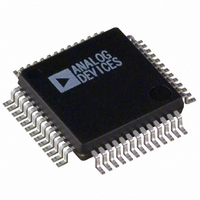
ADUC834BSZ Analog Devices Inc, ADUC834BSZ Datasheet - Page 36

ADUC834BSZ
Manufacturer Part Number
ADUC834BSZ
Description
IC ADC DUAL16/24BIT W/MCU 52MQFP
Manufacturer
Analog Devices Inc
Series
MicroConverter® ADuC8xxr
Specifications of ADUC834BSZ
Core Size
8-Bit
Program Memory Size
62KB (62K x 8)
Oscillator Type
Internal
Core Processor
8052
Speed
12.58MHz
Connectivity
EBI/EMI, I²C, SPI, UART/USART
Peripherals
POR, PSM, PWM, Temp Sensor, WDT
Number Of I /o
34
Program Memory Type
FLASH
Eeprom Size
4K x 8
Ram Size
2.25K x 8
Voltage - Supply (vcc/vdd)
2.7 V ~ 5.25 V
Data Converters
A/D 3x16b, 4x24b; D/A 1x12b
Operating Temperature
-40°C ~ 125°C
Package / Case
52-MQFP, 52-PQFP
Controller Family/series
(8052) ADUC
No. Of I/o's
26
Eeprom Memory Size
62KB
Ram Memory Size
2KB
Cpu Speed
12.58MHz
Package
52MQFP
Device Core
8052
Family Name
ADuC8xx
Maximum Speed
12.58 MHz
Operating Supply Voltage
3.3|5 V
Data Bus Width
8 Bit
Number Of Programmable I/os
26
Interface Type
I2C/SPI/UART
On-chip Adc
4-chx16-bit|4-chx24-bit
On-chip Dac
1-chx12-bit
Number Of Timers
3
Lead Free Status / RoHS Status
Lead free / RoHS Compliant
Available stocks
Company
Part Number
Manufacturer
Quantity
Price
Company:
Part Number:
ADUC834BSZ
Manufacturer:
TOSHIBA
Quantity:
1 200
Company:
Part Number:
ADUC834BSZ
Manufacturer:
Analog Devices Inc
Quantity:
10 000
Part Number:
ADUC834BSZ
Manufacturer:
ADI/亚德诺
Quantity:
20 000
ADuC834
PULSEWIDTH MODULATOR (PWM)
The PWM on the ADuC834 is a highly flexible PWM offering
programmable resolution and input clock, and can be config-
ured for any one of six different modes of operation. Two of
these modes allow the PWM to be configured as a - DAC
with up to 16 bits of resolution. A block diagram of the PWM is
shown in Figure 26.
Bit
7
6
5
4
3
2
1
0
32.768kHz/15
12.583MHz
32.768kHz
PWM
Name
–––
MD2
MD1
MD0
CDIV1
CDIV0
CSEL1
CSEL0
CLK
Figure 26. PWM Block Diagram
SELECT
CLOCK
Description
Reserved for Future Use
PWM Mode Bits
The MD2/1/0 bits choose the PWM mode as follows:
MD2
0
0
0
0
1
1
1
1
PWM Clock Divider
Scale the clock source for the PWM counter as follows:
CDIV1
0
0
1
1
PWM Clock Divider
Select the clock source for the PWM as follows:
CSEL1
0
0
1
1
MODE
16-BIT PWM COUNTER
PROGRAMMABLE
COMPARE
PWM0H/L
DIVIDER
Table XVI. PWMCON SFR Bit Designations
PWM1H/L
P1.0
P1.1
MD1
0
0
1
1
0
0
1
1
CDIV0 Description
0
1
0
1
CSEL0 Description
0
1
0
1
–36–
MD0
0
1
0
1
0
1
0
1
PWM Counter = Selected Clock /1
PWM Counter = Selected Clock /4
PWM Counter = Selected Clock /16
PWM Counter = Selected Clock /64
PWM Clock = f
PWM Clock = f
PWM Clock = External Input at P3.4/T0/PWMCLK
PWM Clock = f
The PWM uses five SFRs: the control SFR, PWMCON, and four
data SFRs PWM0H, PWM0L, PWM1H, and PWM1L.
PWMCON (as described below) controls the different modes of
operation of the PWM as well as the PWM clock frequency.
PWM0H/L and PWM1H/L are the data registers that determine
the duty cycles of the PWM outputs at P1.0 and P1.1.
To use the PWM user software, first write to PWMCON to
select the PWM mode of operation and the PWM input clock.
Writing to PWMCON also resets the PWM counter. In any of
the 16-bit modes of operation (Modes 1, 3, 4, 6), user software
should write to the PWM0L or PWM1L SFRs first. This value
is written to a hidden SFR. Writing to the PWM0H or PWM1H
SFRs updates both the PWMxH and the PWMxL SFRs but
does not change the outputs until the end of the PWM cycle in
progress. The values written to these 16-bit registers are then
used in the next PWM cycle.
PWMCON
SFR Address
Power-On Default Value
Bit Addressable
Mode
Mode 0: PWM Disabled
Mode 1: Single Variable Resolution PWM
Mode 2: Twin 8-bit PWM
Mode 3: Twin 16-bit PWM
Mode 4: Dual NRZ 16-bit - DAC
Mode 5: Dual 8-bit PWM
Mode 6: Dual RZ 16-bit - DAC
Reserved for Future Use
XTAL
XTAL
VCO
(12.58 MHz)
/15
PWM Control SFR
AEH
00H
No
REV. A


