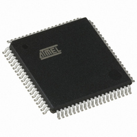
AT89C5132-ROTUL Atmel, AT89C5132-ROTUL Datasheet - Page 92

AT89C5132-ROTUL
Manufacturer Part Number
AT89C5132-ROTUL
Description
IC 8051 MCU FLASH 64K USB 80TQFP
Manufacturer
Atmel
Series
AT89C513xr
Specifications of AT89C5132-ROTUL
Core Processor
C52X2
Core Size
8-Bit
Speed
20MHz
Connectivity
IDE/ATAPI, I²C, MMC, PCM, SPI, UART/USART, USB
Peripherals
I²S, POR, WDT
Number Of I /o
44
Program Memory Size
64KB (64K x 8)
Program Memory Type
FLASH
Eeprom Size
4K x 8
Ram Size
2.25K x 8
Voltage - Supply (vcc/vdd)
2.7 V ~ 3.3 V
Data Converters
A/D 2x10b
Oscillator Type
Internal
Operating Temperature
-40°C ~ 85°C
Package / Case
80-TQFP, 80-VQFP
Cpu Family
89C
Device Core
8051
Device Core Size
8b
Frequency (max)
40MHz
Interface Type
IDE/SPI/UART/USB
Total Internal Ram Size
2.25KB
# I/os (max)
44
Number Of Timers - General Purpose
2
Operating Supply Voltage (typ)
3V
Operating Supply Voltage (max)
3.3V
Operating Supply Voltage (min)
2.7V
On-chip Adc
2-chx10-bit
Instruction Set Architecture
CISC
Operating Temp Range
-40C to 85C
Operating Temperature Classification
Industrial
Mounting
Surface Mount
Pin Count
80
Package Type
TQFP
Package
80TQFP
Family Name
89C
Maximum Speed
40 MHz
Operating Supply Voltage
3 V
Data Bus Width
8 Bit
Number Of Programmable I/os
44
Number Of Timers
2
Maximum Clock Frequency
20 MHz
Data Ram Size
2304 B
Mounting Style
SMD/SMT
A/d Bit Size
10 bit
A/d Channels Available
2
Height
1.45 mm
Length
14.1 mm
Maximum Operating Temperature
+ 85 C
Minimum Operating Temperature
- 40 C
Supply Voltage (max)
3.3 V
Supply Voltage (min)
2.7 V
Width
14.1 mm
For Use With
AT89OCD-01 - USB EMULATOR FOR AT8XC51 MCU
Lead Free Status / RoHS Status
Lead free / RoHS Compliant
Available stocks
Company
Part Number
Manufacturer
Quantity
Price
16.6.3
16.6.3.1
16.6.3.2
16.6.3.3
16.6.3.4
92
AT89C5132
Data Transmitter
Configuration
Data Loading
Data Transmission
End of Transmission
Figure 16-15. Data Controller Configuration Flows
For transmitting data to the card, user must first configure the data controller in transmission
mode by setting the DATDIR bit in MMCON1 register.
Figure 16-16 summarizes the data stream transmission flows in both polling and interrupt modes
while Figure 16-17 summarizes the data block transmission flows in both polling and interrupt
modes, these flows assume that block length is greater than 16 data.
Data is loaded in the FIFO by writing to MMDAT register. Number of data loaded may vary from
1 to 16 Bytes. Then if necessary (more than 16 Bytes to send) user must wait that one FIFO
becomes empty (F1EI or F2EI set) before loading 8 new data.
Transmission is enabled by setting and clearing DATEN bit in MMCON1 register.
Data is transmitted immediately if the response has already been received, or is delayed after
the response reception if its status is correct. In both cases transmission is delayed if a card
sends a busy state on the data line until the end of this busy condition.
According to the MMC specification, the data transfer from the host to the card may not start
sooner than 2 MMC clock periods after the card response was received (formally N
ter). To address all card types, this delay can be programmed using DATD1:0 Bits in MMCON2
register from 3 MMC clock periods when DATD1:0 Bits are cleared to 9 MMC clock periods
when DATD2:0 Bits are set, by step of 2 MMC clock periods.
The end of data frame (block or stream) transmission is signalled by the EOFI flag in MMINT
register. This flag may generate an MMC interrupt request as detailed in Section "Interrupt",
page 96.
In data stream mode, EOFI flag is set, after reception of the End bit. This assumes user has pre-
viously sent the STOP command to the card, which is the only way to stop stream transfer.
In data block mode, EOFI flag is set, after reception of the CRC status token (see Figure 16-4).
Two other flags in MMSTA register: DATFS and CRC16S report a status on the frame sent.
DATFS indicates if the CRC status token format is correct or not, and CRC16S indicates if the
card has found the CRC16 of the block correct or not.
Configure Format
Configuration
Data Stream
DFMT = 0
Data Single Block
Configure Format
BLEN3:0 = XXXXb
Configuration
MBLOCK = 0
DFMT = 1
Data Multi-block
Configure Format
BLEN3:0 = XXXXb
Configuration
MBLOCK = 1
DFMT = 1
4173E–USB–09/07
WR
parame-


