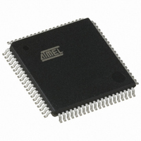
AT89C5132-ROTUL Atmel, AT89C5132-ROTUL Datasheet - Page 77

AT89C5132-ROTUL
Manufacturer Part Number
AT89C5132-ROTUL
Description
IC 8051 MCU FLASH 64K USB 80TQFP
Manufacturer
Atmel
Series
AT89C513xr
Specifications of AT89C5132-ROTUL
Core Processor
C52X2
Core Size
8-Bit
Speed
20MHz
Connectivity
IDE/ATAPI, I²C, MMC, PCM, SPI, UART/USART, USB
Peripherals
I²S, POR, WDT
Number Of I /o
44
Program Memory Size
64KB (64K x 8)
Program Memory Type
FLASH
Eeprom Size
4K x 8
Ram Size
2.25K x 8
Voltage - Supply (vcc/vdd)
2.7 V ~ 3.3 V
Data Converters
A/D 2x10b
Oscillator Type
Internal
Operating Temperature
-40°C ~ 85°C
Package / Case
80-TQFP, 80-VQFP
Cpu Family
89C
Device Core
8051
Device Core Size
8b
Frequency (max)
40MHz
Interface Type
IDE/SPI/UART/USB
Total Internal Ram Size
2.25KB
# I/os (max)
44
Number Of Timers - General Purpose
2
Operating Supply Voltage (typ)
3V
Operating Supply Voltage (max)
3.3V
Operating Supply Voltage (min)
2.7V
On-chip Adc
2-chx10-bit
Instruction Set Architecture
CISC
Operating Temp Range
-40C to 85C
Operating Temperature Classification
Industrial
Mounting
Surface Mount
Pin Count
80
Package Type
TQFP
Package
80TQFP
Family Name
89C
Maximum Speed
40 MHz
Operating Supply Voltage
3 V
Data Bus Width
8 Bit
Number Of Programmable I/os
44
Number Of Timers
2
Maximum Clock Frequency
20 MHz
Data Ram Size
2304 B
Mounting Style
SMD/SMT
A/d Bit Size
10 bit
A/d Channels Available
2
Height
1.45 mm
Length
14.1 mm
Maximum Operating Temperature
+ 85 C
Minimum Operating Temperature
- 40 C
Supply Voltage (max)
3.3 V
Supply Voltage (min)
2.7 V
Width
14.1 mm
For Use With
AT89OCD-01 - USB EMULATOR FOR AT8XC51 MCU
Lead Free Status / RoHS Status
Lead free / RoHS Compliant
Available stocks
Company
Part Number
Manufacturer
Quantity
Price
4173E–USB–09/07
Reset Value = 0000 0000b
Table 63. UEPRST Register
UEPRST (S:D5h) – USB Endpoint FIFO Reset Register
Number
Bit
7
7
6
5
4
3
2
1
0
-
Mnemonic Description
RXSETUP
STALLRQ
STLCRC
TXRDY
RXOUT
TXCMP
DIR
Bit
6
-
-
Control Endpoint Direction Bit
This bit is relevant only if the endpoint is configured in Control type.
Set for the data stage. Clear otherwise.
Note: This bit should be configured on RXSETUP interrupt before any other bit is
changed. This also determines the status phase (IN for a control write and OUT
for a control read). This bit should be cleared for status stage of a Control Out
transaction.
Reserved
The values read from this Bits are always 0. Do not set this bit.
Stall Handshake Request Bit
Set to send a STALL answer to the host for the next handshake.Clear otherwise.
TX Packet Ready Control Bit
Set after a packet has been written into the endpoint FIFO for IN data transfers.
Data shall be written into the endpoint FIFO only after this bit has been cleared.
Set this bit without writing data to the endpoint FIFO to send a Zero Length
Packet, which is generally recommended and may be required to terminate a
transfer when the length of the last data packet is equal to MaxPacketSize (e.g.,
for control read transfers).
Cleared by hardware, as soon as the packet has been sent for Isochronous
endpoints, or after the host has acknowledged the packet for Control, Bulk and
Interrupt endpoints.
Stall Sent Interrupt Flag/CRC Error Interrupt Flag
For Control, Bulk and Interrupt Endpoints:
Set by hardware after a STALL handshake has been sent as requested by
STALLRQ. Then, the endpoint interrupt is triggered if enabled in UEPIEN.
Cleared by hardware when a SETUP packet is received (see RXSETUP).
For Isochronous Endpoints:
Set by hardware if the last data received is corrupted (CRC error on data). Then,
the endpoint interrupt is triggered if enabled in UEPIEN.
Cleared by hardware when a non corrupted data is received.
Received SETUP Interrupt Flag
Set by hardware when a valid SETUP packet has been received from the host.
Then, all the other Bits of the register are cleared by hardware and the endpoint
interrupt is triggered if enabled in UEPIEN.
Clear by software after reading the SETUP data from the endpoint FIFO.
Received OUT Data Interrupt Flag
Set by hardware after an OUT packet has been received. Then, the endpoint
interrupt is triggered if enabled in UEPIEN and all the following OUT packets to
the endpoint are rejected (NACK’ed) until this bit is cleared. However, for Control
endpoints, an early SETUP transaction may overwrite the content of the endpoint
FIFO, even if its Data packet is received while this bit is set.
Clear by software after reading the OUT data from the endpoint FIFO.
Transmitted IN Data Complete Interrupt Flag
Set by hardware after an IN packet has been transmitted for Isochronous
endpoints and after it has been accepted (ACK’ed) by the host for Control, Bulk
and Interrupt endpoints. Then, the endpoint interrupt is triggered if enabled in
UEPIEN.
Clear by software before setting again TXRDY.
5
-
4
-
EP3RST
3
EP2RST
2
AT89C5132
EP1RST
1
EP0RST
0
77


