AT89C5132-ROTUL Atmel, AT89C5132-ROTUL Datasheet - Page 170
AT89C5132-ROTUL
Manufacturer Part Number
AT89C5132-ROTUL
Description
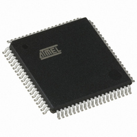
IC 8051 MCU FLASH 64K USB 80TQFP
Manufacturer
Atmel
Series
AT89C513xr
Specifications of AT89C5132-ROTUL
Core Processor
C52X2
Core Size
8-Bit
Speed
20MHz
Connectivity
IDE/ATAPI, I²C, MMC, PCM, SPI, UART/USART, USB
Peripherals
I²S, POR, WDT
Number Of I /o
44
Program Memory Size
64KB (64K x 8)
Program Memory Type
FLASH
Eeprom Size
4K x 8
Ram Size
2.25K x 8
Voltage - Supply (vcc/vdd)
2.7 V ~ 3.3 V
Data Converters
A/D 2x10b
Oscillator Type
Internal
Operating Temperature
-40°C ~ 85°C
Package / Case
80-TQFP, 80-VQFP
Cpu Family
89C
Device Core
8051
Device Core Size
8b
Frequency (max)
40MHz
Interface Type
IDE/SPI/UART/USB
Total Internal Ram Size
2.25KB
# I/os (max)
44
Number Of Timers - General Purpose
2
Operating Supply Voltage (typ)
3V
Operating Supply Voltage (max)
3.3V
Operating Supply Voltage (min)
2.7V
On-chip Adc
2-chx10-bit
Instruction Set Architecture
CISC
Operating Temp Range
-40C to 85C
Operating Temperature Classification
Industrial
Mounting
Surface Mount
Pin Count
80
Package Type
TQFP
Package
80TQFP
Family Name
89C
Maximum Speed
40 MHz
Operating Supply Voltage
3 V
Data Bus Width
8 Bit
Number Of Programmable I/os
44
Number Of Timers
2
Maximum Clock Frequency
20 MHz
Data Ram Size
2304 B
Mounting Style
SMD/SMT
A/d Bit Size
10 bit
A/d Channels Available
2
Height
1.45 mm
Length
14.1 mm
Maximum Operating Temperature
+ 85 C
Minimum Operating Temperature
- 40 C
Supply Voltage (max)
3.3 V
Supply Voltage (min)
2.7 V
Width
14.1 mm
For Use With
AT89OCD-01 - USB EMULATOR FOR AT8XC51 MCU
Lead Free Status / RoHS Status
Lead free / RoHS Compliant
Available stocks
Company
Part Number
Manufacturer
Quantity
Price


23.3.7
23.3.7.1
23.3.7.2
170
AT89C5132
Analog to Digital Converter
Definition of Symbols
Characteristics
Table 120. Analog to Digital Converter Timing Symbol Definitions
Table 37. Analog to Digital Converter AC Characteristics
V
Notes:
T
T
T
DLe
ILe
OSe
Ge
DD
CLCL
EHSH
SHSL
= 2.7 to 3.3 V, T
Symbol
1. AV
2. The differential non-linearity is the difference between the actual step width and the ideal step
3. The integral non-linearity is the peak difference between the center of the actual step and the
4. The offset error is the absolute difference between the straight line which fits the actual trans-
5. The gain error is the relative difference in percent between the straight line which fits the actual
C
E
S
width (see Figure 23-20).
ideal transfer curve after appropriate adjustment of gain and offset errors (see Figure 23-20).
fer curve (after removing of gain error), and the straight line which fits the ideal transfer curve
(see Figure 23-20).
transfer curve (after removing of offset error), and the straight line which fits the ideal transfer
curve (see Figure 23-20).
DD
Signals
= AV
Clock
Enable (ADEN bit)
Start Conversion
(ADSST bit)
Clock Period
Start-up Time
Conversion Time
Differential non-
linearity error
Integral non-linearity
errorss
Offset error
Gain error
REFP
A
= -40 to +85°C
= 3.0 V, AV
Parameter
(1)(3)
(1)(5)
(1)(4)
(1)(2)
SS
= AV
REFN
= 0 V. ADC is monotonic with no missing code.
Min
4
11·T
Max
H
L
4
1
2
4
4
CLCL
Conditions
High
Low
4173E–USB–09/07
Unit
LSB
LSB
LSB
LSB
µs
µs
µs
Related parts for AT89C5132-ROTUL
Image
Part Number
Description
Manufacturer
Datasheet
Request
R

Part Number:
Description:
Manufacturer:
Atmel Corporation
Datasheet:

Part Number:
Description:
MCU 8051 FLASH USB 80TQFP
Manufacturer:
Atmel
Datasheet:
Part Number:
Description:
IC 8051 MCU FLASH 64K USB 80TQFP
Manufacturer:
Atmel
Datasheet:

Part Number:
Description:
DEV KIT FOR AVR/AVR32
Manufacturer:
Atmel
Datasheet:
Part Number:
Description:
INTERVAL AND WIPE/WASH WIPER CONTROL IC WITH DELAY
Manufacturer:
ATMEL Corporation
Datasheet:
Part Number:
Description:
Low-Voltage Voice-Switched IC for Hands-Free Operation
Manufacturer:
ATMEL Corporation
Datasheet:
Part Number:
Description:
MONOLITHIC INTEGRATED FEATUREPHONE CIRCUIT
Manufacturer:
ATMEL Corporation
Datasheet:
Part Number:
Description:
AM-FM Receiver IC U4255BM-M
Manufacturer:
ATMEL Corporation
Datasheet:
Part Number:
Description:
Monolithic Integrated Feature Phone Circuit
Manufacturer:
ATMEL Corporation
Datasheet:
Part Number:
Description:
Multistandard Video-IF and Quasi Parallel Sound Processing
Manufacturer:
ATMEL Corporation
Datasheet:
Part Number:
Description:
High-performance EE PLD
Manufacturer:
ATMEL Corporation
Datasheet:
Part Number:
Description:
8-bit Flash Microcontroller
Manufacturer:
ATMEL Corporation
Datasheet: