STEVAL-ISB005V1 STMicroelectronics, STEVAL-ISB005V1 Datasheet - Page 98
STEVAL-ISB005V1
Manufacturer Part Number
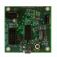
STEVAL-ISB005V1
Description
BOARD EVAL CHARGER ST7260/L6924D
Manufacturer
STMicroelectronics
Type
Battery Managementr
Specifications of STEVAL-ISB005V1
Main Purpose
Power Management, Battery Charger
Embedded
Yes, MCU, 8-Bit
Utilized Ic / Part
L6924, ST72F63BK6M1
Primary Attributes
1 Cell- Li-Ion / Li-Pol, 5 V (USB Input)
Secondary Attributes
Powered by Wall Adaptor Also, LED Status Indicators
Input Voltage
5 V
Product
Power Management Modules
Lead Free Status / RoHS Status
Lead free / RoHS Compliant
For Use With/related Products
L6924D, ST7260
Other names
497-8428
Available stocks
Company
Part Number
Manufacturer
Quantity
Price
Company:

Part Number:
STEVAL-ISB005V1
Manufacturer:
STMicroelectronics
Quantity:
1


USB interface (USB)
14.5.2
14.5.3
Note:
14.5.4
98/139
1.
2.
3.
4.
Initializing DMA buffers
The DMA buffers are a contiguous zone of memory whose maximum size is 48 bytes. They
can be placed anywhere in the memory space to enable the reception of messages. The 10
most significant bits of the start of this memory area are specified by bits DA15-DA6 in
registers DMAR and IDR, the remaining bits are 0. The memory map is shown in
Each buffer is filled starting from the bottom (last 3 address bits=000) up.
Endpoint initialization
To be ready to receive:
Set STAT_RX to VALID (11b) in EP0RB to enable reception.
To be ready to transmit:
1.
2.
3.
Once transmission and/or reception are enabled, registers EPnRA and/or EPnRB
(respectively) must not be modified by software, as the hardware can change their value on
the fly.
When the operation is completed, they can be accessed again to enable a new operation.
Interrupt handling
Start of frame (SOF)
The interrupt service routine may monitor the SOF events for a 1 ms synchronization event
to the USB bus. This interrupt is generated at the end of a resume sequence and can also
be used to detect this event.
USB reset (RESET)
When this event occurs, the DADDR register is reset, and communication is disabled in all
endpoint registers (the USB interface will not respond to any packet). Software is
responsible for reenabling endpoint 0 within 10 ms of the end of reset. To do this, set the
STAT_RX bits in the EP0RB register to VALID.
Suspend (SUSP)
The CPU is warned about the lack of bus activity for more than 3 ms, which is a suspend
request. The software should set the USB interface to suspend mode and execute an ST7
HALT instruction to meet the USB-specified power constraints.
Initialize the DMAR, IDR, and IMR registers (choice of enabled interrupts, address of
DMA buffers). Refer the paragraph titled initializing the DMA Buffers.
Initialize the EP0RA and EP0RB registers to enable accesses to address 0 and
endpoint 0 to support USB enumeration. Refer to the paragraph titled Endpoint
Initialization.
When addresses are received through this channel, update the content of the DADDR.
If needed, write the endpoint numbers in the EA fields in the EP1RB and EP2RB
register.
Write the data in the DMA transmit buffer.
In register EPnRA, specify the number of bytes to be transmitted in the TBC field
Enable the endpoint by setting the STAT_TX bits to VALID (11b) in EPnRA.
ST7260xx
Figure
42.
Related parts for STEVAL-ISB005V1
Image
Part Number
Description
Manufacturer
Datasheet
Request
R

Part Number:
Description:
BOARD RGB CTR ST7,STP08C596MTR
Manufacturer:
STMicroelectronics
Datasheet:

Part Number:
Description:
Power Management IC Development Tools Full Speed USB to RS232 Bridge Demo
Manufacturer:
STMicroelectronics
Datasheet:
Part Number:
Description:
Power Management IC Development Tools 2.5W solar eval BRD USB SPV1040 LD39050
Manufacturer:
STMicroelectronics
Datasheet:

Part Number:
Description:
BOARD EVAL FOR MEMS SENSORS
Manufacturer:
STMicroelectronics
Datasheet:

Part Number:
Description:
KIT DEV STARTER ST10F276Z5
Manufacturer:
STMicroelectronics
Datasheet:

Part Number:
Description:
BOARD EVAL HDMI $ VIDEO SWITCH
Manufacturer:
STMicroelectronics
Datasheet:

Part Number:
Description:
BOARD DEMO ACCELEROMETER DIL24
Manufacturer:
STMicroelectronics
Datasheet:

Part Number:
Description:
BOARD STLM75/STDS75/ST72F651
Manufacturer:
STMicroelectronics
Datasheet:

Part Number:
Description:
EVAL BOARD 3AXIS MEMS ACCELLRMTR
Manufacturer:
STMicroelectronics
Datasheet:

Part Number:
Description:
BOARD EVAL 8BIT MICRO + TDE1708
Manufacturer:
STMicroelectronics
Datasheet:
Part Number:
Description:
STMicroelectronics [RIPPLE-CARRY BINARY COUNTER/DIVIDERS]
Manufacturer:
STMicroelectronics
Datasheet:
Part Number:
Description:
STMicroelectronics [LIQUID-CRYSTAL DISPLAY DRIVERS]
Manufacturer:
STMicroelectronics
Datasheet:
Part Number:
Description:
BOARD EVAL FOR MEMS SENSORS
Manufacturer:
STMicroelectronics
Datasheet: