STEVAL-ISB005V1 STMicroelectronics, STEVAL-ISB005V1 Datasheet - Page 111
STEVAL-ISB005V1
Manufacturer Part Number
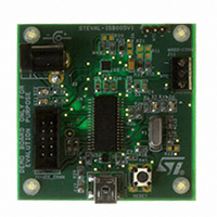
STEVAL-ISB005V1
Description
BOARD EVAL CHARGER ST7260/L6924D
Manufacturer
STMicroelectronics
Type
Battery Managementr
Specifications of STEVAL-ISB005V1
Main Purpose
Power Management, Battery Charger
Embedded
Yes, MCU, 8-Bit
Utilized Ic / Part
L6924, ST72F63BK6M1
Primary Attributes
1 Cell- Li-Ion / Li-Pol, 5 V (USB Input)
Secondary Attributes
Powered by Wall Adaptor Also, LED Status Indicators
Input Voltage
5 V
Product
Power Management Modules
Lead Free Status / RoHS Status
Lead free / RoHS Compliant
For Use With/related Products
L6924D, ST7260
Other names
497-8428
Available stocks
Company
Part Number
Manufacturer
Quantity
Price
Company:

Part Number:
STEVAL-ISB005V1
Manufacturer:
STMicroelectronics
Quantity:
1


ST7260xx
16.2
Absolute maximum ratings
Stresses above those listed as “absolute maximum ratings” may cause permanent damage
to the device. This is a stress rating only and functional operation of the device under these
conditions is not implied. Exposure to maximum rating conditions for extended periods may
affect device reliability.
Table 55.
1. Directly connecting the RESET and I/O pins to V
Table 56.
1. All power (V
2. I
3. When several inputs are submitted to a current injection, the maximum ΣI
4. True open drain I/O port pins do not accept positive injection.
internal reset is generated or an unexpected change of the I/O configuration occurs (for example, due to a
corrupted program counter). To guarantee safe operation, this connection has to be done through a pull-up
or pull-down resistor (typical: 4.7kΩ for RESET, 10kΩ for I/Os). Unused I/O pins must be tied in the same
way to V
cannot be respected, the injection current must be limited externally to the I
injection is induced by V
there is no positive injection current, and the corresponding V
positive and negative injected currents (instantaneous values). These results are based on
characterization with ΣI
INJ(PIN)
ΣI
V
I
I
V
V
INJ(PIN)
INJ(PIN)
Symbol
Symbol
INJ(PIN)
ESD(HBM)
DD
IN
I
I
(1) & (2)
VDD
VSS
I
IO
- V
must never be exceeded. This is implicitly insured if V
DD
SS
(2)
(2)
or V
Voltage characteristics
Current characteristics
(2)
DD
) and ground (V
SS
according to their reset configuration.
Supply voltage
Input voltage on true open drain pins
Input voltage on any other pin
Electro-static discharge voltage (Human Body
Model)
Total current into V
Total current out of V
Output current sunk by any standard I/O and
control pin
Output current sunk by any high sink I/O pin
Output current source by any I/Os and control pin
Injected current on V
Injected current on RESET pin
Injected current on OSCIN and OSCOUT pins
Injected current on any other pin
Total injected current (sum of all I/O and control
pins)
Negative injected current to PB0(10mA) pin
INJ(PIN)
IN
>V
(3)
DD
SS
maximum current injection on four I/O port pins of the device.
while a negative injection is induced by V
) lines must always be connected to the external supply.
DD
Ratings
Ratings
SS
PP
power lines (source)
ground lines (sink)
pin
DD
or V
SS
(3) & (4)
could damage the device if an unintentional
IN
IN
maximum must always be respected
maximum is respected. If V
(1)
(1)
IN
INJ(PIN)
<V
INJ(PIN)
ratings (electrical sensitivity)”
V
SS
Electrical characteristics
Maximum value
SS
See “Absolute maximum
V
Maximum value
. For true open-drain pads,
-0.3 to V
is the absolute sum of the
SS
-0.3 to 6.0
value. A positive
6.0
on page 119.
± 20
- 25
- 80
± 5
± 5
± 5
± 5
80
80
25
50
DD
+0.3
IN
maximum
111/139
Unit
Unit
mA
µA
V
Related parts for STEVAL-ISB005V1
Image
Part Number
Description
Manufacturer
Datasheet
Request
R

Part Number:
Description:
BOARD RGB CTR ST7,STP08C596MTR
Manufacturer:
STMicroelectronics
Datasheet:

Part Number:
Description:
Power Management IC Development Tools Full Speed USB to RS232 Bridge Demo
Manufacturer:
STMicroelectronics
Datasheet:
Part Number:
Description:
Power Management IC Development Tools 2.5W solar eval BRD USB SPV1040 LD39050
Manufacturer:
STMicroelectronics
Datasheet:

Part Number:
Description:
BOARD EVAL FOR MEMS SENSORS
Manufacturer:
STMicroelectronics
Datasheet:

Part Number:
Description:
KIT DEV STARTER ST10F276Z5
Manufacturer:
STMicroelectronics
Datasheet:

Part Number:
Description:
BOARD EVAL HDMI $ VIDEO SWITCH
Manufacturer:
STMicroelectronics
Datasheet:

Part Number:
Description:
BOARD DEMO ACCELEROMETER DIL24
Manufacturer:
STMicroelectronics
Datasheet:

Part Number:
Description:
BOARD STLM75/STDS75/ST72F651
Manufacturer:
STMicroelectronics
Datasheet:

Part Number:
Description:
EVAL BOARD 3AXIS MEMS ACCELLRMTR
Manufacturer:
STMicroelectronics
Datasheet:

Part Number:
Description:
BOARD EVAL 8BIT MICRO + TDE1708
Manufacturer:
STMicroelectronics
Datasheet:
Part Number:
Description:
STMicroelectronics [RIPPLE-CARRY BINARY COUNTER/DIVIDERS]
Manufacturer:
STMicroelectronics
Datasheet:
Part Number:
Description:
STMicroelectronics [LIQUID-CRYSTAL DISPLAY DRIVERS]
Manufacturer:
STMicroelectronics
Datasheet:
Part Number:
Description:
BOARD EVAL FOR MEMS SENSORS
Manufacturer:
STMicroelectronics
Datasheet: