MA240017 Microchip Technology, MA240017 Datasheet - Page 247
MA240017
Manufacturer Part Number
MA240017
Description
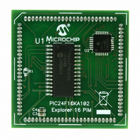
MODULE PLUG-IN PIC24F16KA102 PIM
Manufacturer
Microchip Technology
Series
PIC®r
Specifications of MA240017
Accessory Type
Plug-In Module (PIM) - PIC24F16KA102
Product
Microcontroller Modules
Data Bus Width
16 bit
Core Processor
PIC24F16KA102
Operating Supply Voltage
3 V to 3.6 V
Development Tools By Supplier
Integrated Development Environment, Assembler, ANSI C Compiler
Processor Series
PIC24F
Silicon Manufacturer
Microchip
Core Architecture
PIC
Core Sub-architecture
PIC24
Silicon Core Number
PIC24F
Silicon Family Name
PIC24FxxKAxx
Lead Free Status / RoHS Status
Lead free / RoHS Compliant
For Use With/related Products
Explorer 16 (DM240001 or DM240002)
For Use With
DM240001 - BOARD DEMO PIC24/DSPIC33/PIC32
Lead Free Status / Rohs Status
Lead free / RoHS Compliant
Available stocks
Company
Part Number
Manufacturer
Quantity
Price
Company:

Part Number:
MA240017
Manufacturer:
MICROCHIP
Quantity:
12 000


INDEX
A
A/D
A/D Converter
AC Characteristics
Assembler
B
Basic Connection Requirements ........................................ 15
Baud Rate Generator
Block Diagrams
© 2009 Microchip Technology Inc.
10-Bit High-Speed A/D Converter ............................ 169
Conversion Timing Requirements ............................ 229
Module Specifications .............................................. 228
Reset, Watchdog Timer, Oscillator Start-up Timer,
Analog Input Model .................................................. 176
Transfer Function ..................................................... 177
Capacitive Loading Requirements on
Comparator .............................................................. 227
Comparator Voltage Reference Settling Time ......... 227
CTMU Current Source ............................................. 227
Internal RC Accuracy ............................................... 225
Load Conditions and Requirements ......................... 223
Temperature and Voltage Specifications ................. 223
MPASM Assembler .................................................. 200
Setting as a Bus Master ........................................... 137
10-Bit High-Speed A/D Converter ............................ 170
16-Bit Timer1 ........................................................... 111
Accessing Program Memory with
CALL Stack Frame ..................................................... 37
Comparator Module ................................................. 179
Comparator Voltage Reference ............................... 183
CPU Programmer’s Model ......................................... 21
CRC Reconfigured for Polynomial ........................... 164
CRC Shifter Details .................................................. 163
CTMU Connections and Internal Configuration
CTMU Typical Connections and Internal
CTMU Typical Connections and Internal
Data Access From Program Space
High/Low-Voltage Detect (HLVD) ............................ 167
I
Individual Comparator Configurations ...................... 180
Input Capture ........................................................... 119
Output Compare ...................................................... 124
PIC24F CPU Core ..................................................... 20
PIC24F16KA102 Family (General) ............................ 10
PSV Operation ........................................................... 41
Reset System ............................................................. 57
RTCC ....................................................................... 151
Shared I/O Port Structure ........................................ 109
Simplified UART ....................................................... 143
SPI1 Module (Enhanced Buffer Mode) .................... 129
SPI1 Module (Standard Buffer Mode) ...................... 128
System Clock ............................................................. 91
Timer2 (16-Bit Synchronous Mode) ......................... 115
Timer2/3 (32-Bit Mode) ............................................ 114
2
C Module ............................................................... 136
Power-up Timer and Brown-out Reset
Timing Requirements ....................................... 230
Output Pins ...................................................... 223
for Capacitance Measurement ......................... 185
Configuration for Pulse Delay Generation ....... 186
Configuration for Time Measurement .............. 186
Address Generation ........................................... 38
Table Instructions ............................................. 40
Preliminary
PIC24F16KA102 FAMILY
Brown-out Reset
Brown-out Reset (BOR) ..................................................... 61
C
C Compilers
Charge Time Measurement Unit. See CTMU.
Code Examples
Code Protection ............................................................... 197
Comparator ...................................................................... 179
Comparator Voltage Reference ....................................... 183
Configuration Bits ............................................................ 189
Configuration of Analog, Digital Pins
Core Features ...................................................................... 7
CPU
CRC
CTMU
Customer Change Notification Service ............................ 249
Customer Notification Service ......................................... 249
Customer Support ............................................................ 249
Timer3 (16-Bit Synchronous Mode) ......................... 115
Watchdog Timer (WDT) ........................................... 196
Trip Points ............................................................... 214
MPLAB C18 ............................................................. 200
MPLAB C30 ............................................................. 200
Data EEPROM Bulk Erase ........................................ 55
Data EEPROM Unlock Sequence ............................. 51
Erasing a Program Memory Row,
Erasing a Program Memory Row,
I/O Port Write/Read ................................................. 110
Initiating a Programming Sequence,
Initiating a Programming Sequence,
Loading the Write Buffers,
Loading the Write Buffers,
Programming a Single Word of
PWRSAV Instruction Syntax ................................... 101
Reading the Data EEPROM Using the
Sequence for Clock Switching ................................... 98
Setting the RTCWREN Bit ....................................... 152
Single-Word Erase .................................................... 54
Single-Word Write to Data EEPROM ........................ 55
During ICSP Operation .............................................. 18
ALU ............................................................................ 23
Control Registers ....................................................... 22
Core Registers ........................................................... 20
Programmer’s Model ................................................. 19
Operation in Power Save Modes ............................. 164
User Interface .......................................................... 164
Measuring Capacitance ........................................... 185
Measuring Time ....................................................... 186
Pulse Delay and Generation .................................... 186
’C’ Language Code ............................................ 47
Assembly Language Code ................................ 46
’C’ Language Code ............................................ 49
Assembly Language Code ................................ 49
’C’ Language Code ............................................ 48
Assembly Language Code ................................ 48
Flash Program Memory ..................................... 49
TBLRD Command ............................................. 56
DS39927B-page 245
Related parts for MA240017
Image
Part Number
Description
Manufacturer
Datasheet
Request
R

Part Number:
Description:
Manufacturer:
Microchip Technology Inc.
Datasheet:
Part Number:
Description:
Manufacturer:
Microchip Technology Inc.
Datasheet:
Part Number:
Description:
Manufacturer:
Microchip Technology Inc.
Datasheet:
Part Number:
Description:
Manufacturer:
Microchip Technology Inc.
Datasheet:
Part Number:
Description:
Manufacturer:
Microchip Technology Inc.
Datasheet:
Part Number:
Description:
Manufacturer:
Microchip Technology Inc.
Datasheet:
Part Number:
Description:
Manufacturer:
Microchip Technology Inc.
Datasheet:
Part Number:
Description:
Manufacturer:
Microchip Technology Inc.
Datasheet: