MA240017 Microchip Technology, MA240017 Datasheet - Page 129
MA240017
Manufacturer Part Number
MA240017
Description
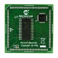
MODULE PLUG-IN PIC24F16KA102 PIM
Manufacturer
Microchip Technology
Series
PIC®r
Specifications of MA240017
Accessory Type
Plug-In Module (PIM) - PIC24F16KA102
Product
Microcontroller Modules
Data Bus Width
16 bit
Core Processor
PIC24F16KA102
Operating Supply Voltage
3 V to 3.6 V
Development Tools By Supplier
Integrated Development Environment, Assembler, ANSI C Compiler
Processor Series
PIC24F
Silicon Manufacturer
Microchip
Core Architecture
PIC
Core Sub-architecture
PIC24
Silicon Core Number
PIC24F
Silicon Family Name
PIC24FxxKAxx
Lead Free Status / RoHS Status
Lead free / RoHS Compliant
For Use With/related Products
Explorer 16 (DM240001 or DM240002)
For Use With
DM240001 - BOARD DEMO PIC24/DSPIC33/PIC32
Lead Free Status / Rohs Status
Lead free / RoHS Compliant
Available stocks
Company
Part Number
Manufacturer
Quantity
Price
Company:

Part Number:
MA240017
Manufacturer:
MICROCHIP
Quantity:
12 000


16.0
The Serial Peripheral Interface (SPI) module is a
synchronous serial interface useful for communicating
with other peripheral or microcontroller devices. These
peripheral devices may be serial data EEPROMs, shift
registers, display drivers, A/D Converters, etc. The SPI
module is compatible with Motorola’s SPI and SIOP
interfaces.
The module supports operation in two buffer modes. In
Standard mode, data is shifted through a single serial
buffer. In Enhanced Buffer mode, data is shifted
through an 8-level FIFO buffer.
The module also supports a basic framed SPI protocol
while operating in either Master or Slave mode. A total
of four framed SPI configurations are supported.
The SPI serial interface consists of four pins:
• SDI1: Serial Data Input
• SDO1: Serial Data Output
• SCK1: Shift Clock Input or Output
• SS1: Active-Low Slave Select or Frame
The SPI module can be configured to operate using 2,
3 or 4 pins. In the 3-pin mode, SS1 is not used. In the
2-pin mode, both SDO1 and SS1 are not used.
Block diagrams of the module in Standard and
Enhanced Buffer modes are displayed in Figure 16-1
and Figure 16-2.
© 2009 Microchip Technology Inc.
Note:
Note:
Synchronization I/O Pulse
SERIAL PERIPHERAL
INTERFACE (SPI)
This data sheet summarizes the features of
this group of PIC24F devices. It is not
intended to be a comprehensive reference
source. For more information on the Serial
Peripheral Interface, refer to the “PIC24F
Family Reference Manual”, Section 23.
“Serial
(DS39699).
Do not perform read-modify-write operations
(such as bit-oriented instructions) on the
SPI1BUF register in either Standard or
Enhanced Buffer mode.
Peripheral
Interface
(SPI)”
Preliminary
PIC24F16KA102 FAMILY
The devices of the PIC24F16KA102 family offer one
SPI module on a device.
To set up the SPI module for the Standard Master mode
of operation:
1.
2.
3.
4.
5.
To set up the SPI module for the Standard Slave mode
of operation:
1.
2.
3.
4.
5.
6.
7.
Note:
If using interrupts:
a)
b)
c)
Write the desired settings to the SPI1CON1 and
SPI1CON2 registers with the MSTEN bit
(SPI1CON1<5>) = 1.
Clear the SPIROV bit (SPI1STAT<6>).
Enable SPI operation by setting the SPIEN bit
(SPI1STAT<15>).
Write the data to be transmitted to the SPI1BUF
register. Transmission (and reception) will start
as soon as data is written to the SPI1BUF
register.
Clear the SPI1BUF register.
If using interrupts:
a)
b)
c)
Write the desired settings to the SPI1CON1
and SPI1CON2 registers with the MSTEN bit
(SPI1CON1<5>) = 0.
Clear the SMP bit.
If the CKE bit is set, then the SSEN bit
(SPI1CON1<7>) must be set to enable the SS1
pin.
Clear the SPIROV bit (SPI1STAT<6>).
Enable SPI operation by setting the SPIEN bit
(SPI1STAT<15>).
Clear the respective SPI1IF bit in the IFS0
register.
Set the respective SPI1IE bit in the IEC0
register.
Write the respective SPI1IPx bits in the
IPC2 register to set the interrupt priority.
Clear the respective SPI1IF bit in the IFS0
register.
Set the respective SPI1IE bit in the IEC0
register.
Write the respective SPI1IP bits in the IPC2
register to set the interrupt priority.
In this section, the SPI module is referred
to as SPI1, or separately as SPI1. Special
Function Registers (SFRs) will follow a
similar notation. For example, SPI1CON1
or SPI1CON2 refers to the control register
for the SPI1 module.
DS39927B-page 127
Related parts for MA240017
Image
Part Number
Description
Manufacturer
Datasheet
Request
R

Part Number:
Description:
Manufacturer:
Microchip Technology Inc.
Datasheet:
Part Number:
Description:
Manufacturer:
Microchip Technology Inc.
Datasheet:
Part Number:
Description:
Manufacturer:
Microchip Technology Inc.
Datasheet:
Part Number:
Description:
Manufacturer:
Microchip Technology Inc.
Datasheet:
Part Number:
Description:
Manufacturer:
Microchip Technology Inc.
Datasheet:
Part Number:
Description:
Manufacturer:
Microchip Technology Inc.
Datasheet:
Part Number:
Description:
Manufacturer:
Microchip Technology Inc.
Datasheet:
Part Number:
Description:
Manufacturer:
Microchip Technology Inc.
Datasheet: