MA240017 Microchip Technology, MA240017 Datasheet - Page 124
MA240017
Manufacturer Part Number
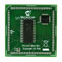
MA240017
Description
MODULE PLUG-IN PIC24F16KA102 PIM
Manufacturer
Microchip Technology
Series
PIC®r
Specifications of MA240017
Accessory Type
Plug-In Module (PIM) - PIC24F16KA102
Product
Microcontroller Modules
Data Bus Width
16 bit
Core Processor
PIC24F16KA102
Operating Supply Voltage
3 V to 3.6 V
Development Tools By Supplier
Integrated Development Environment, Assembler, ANSI C Compiler
Processor Series
PIC24F
Silicon Manufacturer
Microchip
Core Architecture
PIC
Core Sub-architecture
PIC24
Silicon Core Number
PIC24F
Silicon Family Name
PIC24FxxKAxx
Lead Free Status / RoHS Status
Lead free / RoHS Compliant
For Use With/related Products
Explorer 16 (DM240001 or DM240002)
For Use With
DM240001 - BOARD DEMO PIC24/DSPIC33/PIC32
Lead Free Status / Rohs Status
Lead free / RoHS Compliant
Available stocks
Company
Part Number
Manufacturer
Quantity
Price
Company:

Part Number:
MA240017
Manufacturer:
MICROCHIP
Quantity:
12 000


PIC24F16KA102 FAMILY
15.3
The following steps should be taken when configuring
the output compare module for PWM operation:
1.
2.
3.
4.
5.
6.
15.3.1
The PWM period is specified by writing to PRy, the
Timer Period register. The PWM period can be
calculated using Equation 15-1.
EQUATION 15-2:
DS39927B-page 122
Note:
Set the PWM period by writing to the selected
Timer Period register (PRy).
Set the PWM duty cycle by writing to the OC1RS
register.
Write the OC1R register with the initial duty
cycle.
Enable interrupts, if required, for the timer and
output compare modules. The output compare
interrupt is required for PWM Fault pin
utilization.
Configure the output compare module for one of
two PWM Operation modes by writing to the
Output
(OC1CON<2:0>).
Set the TMRy prescale value and enable the
time base by setting TON (TxCON<15>) = 1.
Pulse-Width Modulation (PWM)
Mode
The OC1R register should be initialized
before the output compare module is first
enabled. The OC1R register becomes a
read-only Duty Cycle register when the
module is operated in the PWM modes.
The value held in OC1R will become the
PWM duty cycle for the first PWM period.
The contents of the Output Compare 1
Secondary register, OC1RS, will not be
transferred into OC1R until a time base
period match occurs.
PWM PERIOD
Compare
Note 1: Based on F
Maximum PWM Resolution (bits) =
CALCULATION FOR MAXIMUM PWM RESOLUTION
Mode
bits,
OCM<2:0>
CY
= F
OSC
Preliminary
/2, Doze mode and PLL are disabled.
log
10
(
F
PWM
EQUATION 15-1:
15.3.2
The PWM duty cycle is specified by writing to the
OC1RS register. The OC1RS register can be written to
at any time, but the duty cycle value is not latched into
OC1R until a match between PRy and TMRy occurs
(i.e., the period is complete). This provides a double
buffer for the PWM duty cycle and is essential for
glitchless PWM operation. In PWM mode, OC1R is a
read-only register.
Some important boundary parameters of the PWM duty
cycle include:
• If the Output Compare 1 register, OC1R, is loaded
• If OC1R is greater than PRy (Timer Period
• If OC1R is equal to PRy, the OC1 pin will be low
See Example 15-1 for PWM mode timing details.
Table 15-1 provides an example of PWM frequencies
and resolutions for a device operating at 10 MIPS.
PWM Period = [(PRy) + 1] • T
where:
Note 1:
Note:
with 0000h, the OC1 pin will remain low (0% duty
cycle).
register), the pin will remain high (100% duty
cycle).
for one time base count value and high for all
other count values.
PWM Frequency = 1/[PWM Period]
• (Timer Prescale Value)
log
10
F
CY
(2)
A PRy value of N will produce a PWM
period of N + 1 time base count cycles. For
example, a value of 7 written into the PRy
register will yield a period consisting of
8 time base cycles.
PWM DUTY CYCLE
Based on T
and PLL are disabled.
(1)
CALCULATING THE PWM
PERIOD
CY
© 2009 Microchip Technology Inc.
)
= 2 * T
CY
bits
• (Timer Prescale Value)
(1)
OSC
, Doze mode
Related parts for MA240017
Image
Part Number
Description
Manufacturer
Datasheet
Request
R

Part Number:
Description:
Manufacturer:
Microchip Technology Inc.
Datasheet:
Part Number:
Description:
Manufacturer:
Microchip Technology Inc.
Datasheet:
Part Number:
Description:
Manufacturer:
Microchip Technology Inc.
Datasheet:
Part Number:
Description:
Manufacturer:
Microchip Technology Inc.
Datasheet:
Part Number:
Description:
Manufacturer:
Microchip Technology Inc.
Datasheet:
Part Number:
Description:
Manufacturer:
Microchip Technology Inc.
Datasheet:
Part Number:
Description:
Manufacturer:
Microchip Technology Inc.
Datasheet:
Part Number:
Description:
Manufacturer:
Microchip Technology Inc.
Datasheet: