MA240017 Microchip Technology, MA240017 Datasheet - Page 24
MA240017
Manufacturer Part Number
MA240017
Description
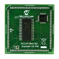
MODULE PLUG-IN PIC24F16KA102 PIM
Manufacturer
Microchip Technology
Series
PIC®r
Specifications of MA240017
Accessory Type
Plug-In Module (PIM) - PIC24F16KA102
Product
Microcontroller Modules
Data Bus Width
16 bit
Core Processor
PIC24F16KA102
Operating Supply Voltage
3 V to 3.6 V
Development Tools By Supplier
Integrated Development Environment, Assembler, ANSI C Compiler
Processor Series
PIC24F
Silicon Manufacturer
Microchip
Core Architecture
PIC
Core Sub-architecture
PIC24
Silicon Core Number
PIC24F
Silicon Family Name
PIC24FxxKAxx
Lead Free Status / RoHS Status
Lead free / RoHS Compliant
For Use With/related Products
Explorer 16 (DM240001 or DM240002)
For Use With
DM240001 - BOARD DEMO PIC24/DSPIC33/PIC32
Lead Free Status / Rohs Status
Lead free / RoHS Compliant
Available stocks
Company
Part Number
Manufacturer
Quantity
Price
Company:

Part Number:
MA240017
Manufacturer:
MICROCHIP
Quantity:
12 000


PIC24F16KA102 FAMILY
3.2
REGISTER 3-1:
DS39927B-page 22
bit 15
bit 7
Legend:
R = Readable bit
-n = Value at POR
bit 15-9
bit 8
bit 7-5
bit 4
bit 3
bit 2
bit 1
bit 0
Note 1:
R/W-0, HSC
IPL2
U-0
—
2:
CPU Control Registers
(2)
The IPL Status bits are read-only when NSTDIS (INTCON1<15>) = 1.
The IPL Status bits are concatenated with the IPL3 bit (CORCON<3>) to form the CPU Interrupt Priority
Level (IPL). The value in parentheses indicates the IPL when IPL3 = 1.
(1)
Unimplemented: Read as ‘0’
DC: ALU Half Carry/Borrow bit
1 = A carry-out from the 4
0 = No carry-out from the 4
IPL<2:0>: CPU Interrupt Priority Level Status bits
111 = CPU interrupt priority level is 7 (15); user interrupts disabled
110 = CPU interrupt priority level is 6 (14)
101 = CPU Interrupt priority Level is 5 (13)
100 = CPU interrupt priority level is 4 (12)
011 = CPU interrupt priority level is 3 (11)
010 = CPU interrupt priority level is 2 (10)
001 = CPU interrupt priority level is 1 (9)
000 = CPU interrupt priority level is 0 (8)
RA: REPEAT Loop Active bit
1 = REPEAT loop in progress
0 = REPEAT loop not in progress
N: ALU Negative bit
1 = Result was negative
0 = Result was non-negative (zero or positive)
OV: ALU Overflow bit
1 = Overflow occurred for signed (2’s complement) arithmetic in this arithmetic operation
0 = No overflow has occurred
Z: ALU Zero bit
1 = An operation, which effects the Z bit, has set it at some time in the past
0 = The most recent operation, which effects the Z bit, has cleared it (i.e., a non-zero result)
C: ALU Carry/Borrow bit
1 = A carry-out from the Most Significant bit (MSb) of the result occurred
0 = No carry-out from the Most Significant bit (MSb) of the result occurred
R/W-0, HSC
IPL1
of the result occurred
SR: ALU STATUS REGISTER
U-0
—
(2)
(1)
HSC = Hardware Settable/Clearable bit
W = Writable bit
‘1’ = Bit is set
R/W-0, HSC
IPL0
U-0
—
(2)
th
th
low-order bit (for byte-sized data) or 8
(1)
or 8
R-0, HSC
Preliminary
th
low-order bit of the result has occurred
U-0
RA
—
U = Unimplemented bit, read as ‘0’
‘0’ = Bit is cleared
R/W-0, HSC R/W-0, HSC R/W-0, HSC R/W-0, HSC
(1,2)
U-0
—
N
U-0
OV
—
th
low-order bit (for word-sized data)
© 2009 Microchip Technology Inc.
x = Bit is unknown
U-0
—
Z
R/W-0, HSC
DC
C
bit 8
bit 0
Related parts for MA240017
Image
Part Number
Description
Manufacturer
Datasheet
Request
R

Part Number:
Description:
Manufacturer:
Microchip Technology Inc.
Datasheet:
Part Number:
Description:
Manufacturer:
Microchip Technology Inc.
Datasheet:
Part Number:
Description:
Manufacturer:
Microchip Technology Inc.
Datasheet:
Part Number:
Description:
Manufacturer:
Microchip Technology Inc.
Datasheet:
Part Number:
Description:
Manufacturer:
Microchip Technology Inc.
Datasheet:
Part Number:
Description:
Manufacturer:
Microchip Technology Inc.
Datasheet:
Part Number:
Description:
Manufacturer:
Microchip Technology Inc.
Datasheet:
Part Number:
Description:
Manufacturer:
Microchip Technology Inc.
Datasheet: