MT8VDDT3264HY-335G3 Micron Technology Inc, MT8VDDT3264HY-335G3 Datasheet - Page 11
MT8VDDT3264HY-335G3
Manufacturer Part Number
MT8VDDT3264HY-335G3
Description
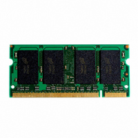
MODULE DDR SDRAM 256MB 200SODIMM
Manufacturer
Micron Technology Inc
Specifications of MT8VDDT3264HY-335G3
Memory Type
DDR SDRAM
Memory Size
256MB
Speed
333MT/s
Package / Case
200-SODIMM
Main Category
DRAM Module
Sub-category
DDR SDRAM
Module Type
200SODIMM
Device Core Size
64b
Organization
32Mx64
Total Density
256MByte
Chip Density
256Mb
Maximum Clock Rate
333MHz
Operating Supply Voltage (typ)
2.5V
Operating Current
1.4A
Number Of Elements
8
Operating Supply Voltage (max)
2.7V
Operating Supply Voltage (min)
2.3V
Operating Temp Range
0C to 70C
Operating Temperature Classification
Commercial
Pin Count
200
Mounting
Socket
Lead Free Status / RoHS Status
Lead free / RoHS Compliant


Commands
Operation Truth Table, provide a general reference of
available commands. For a more detailed description
Table 8:
CKE is HIGH for all commands shown except SELF REFRESH; all states and sequences not shown are illegal or reserved
NOTE:
Table 9:
Used to mask write data; provided coincident with the corresponding data
pdf: 09005aef8092973f, source: 09005aef80921669
DD8C16_32_64x64HG.fm - Rev. B 9/04 EN
NAME (FUNCTION)
NAME (FUNCTION)
DESELECT (NOP)
NO OPERATION (NOP)
ACTIVE (Select device bank and activate row)
READ (Select device bank and column, and start READ burst)
WRITE (Select device bank and column, and start WRITE burst)
BURST TERMINATE
PRECHARGE (Deactivate row in device bank or banks)
AUTO REFRESH or SELF REFRESH (Enter self refresh mode)
LOAD MODE REGISTER
WRITE Enable
WRITE Inhibit
1. DESELECT and NOP are functionally interchangeable.
2. BA0–BA1 provide device bank address and A0–A11 (128MB) or A0–A12 (256MB, 512MB) provide row address.
3. BA0–BA1 provide device bank address; A0–A9 (128MB, 256MB) or A0–A9, A11 (512MB) provide column address; A10
4. Applies only to read bursts with auto precharge disabled; this command is undefined (and should not be used) for READ
5. A10 LOW: BA0–BA1 determine which device bank is precharged. A10 HIGH: all device banks are precharged and BA0-
6. This command is AUTO REFRESH if CKE is HIGH, SELF REFRESH if CKE is LOW.
7. Internal refresh counter controls row addressing; all inputs and I/Os are “Don’t Care” except for CKE.
8. BA0–BA1 select either the mode register or the extended mode register (BA0 = 0, BA1 = 0 select the mode register; BA0
Figure 8, Commands Truth Table, and Figure 9, DM
HIGH enables the auto precharge feature (non-persistent), and A10 LOW disables the auto precharge feature.
bursts with auto precharge enabled and for WRITE bursts.
BA1 are “Don’t Care.”
= 1, BA1 = 0 select extended mode register; other combinations of BA0–BA1 are reserved).
A0–A11 (128MB) or A0–A12 (256MB, 512MB) provide the op-code to be written to the selected mode register.
Commands Truth Table
DM Operation Truth Table
11
of commands and operations, refer to the 128Mb,
256Mb, or 512Mb DDR SDRAM component data sheet.
128MB, 256MB, 512MB (x64, SR)
CS#
H
L
L
L
L
L
L
L
L
Micron Technology, Inc., reserves the right to change products or specifications without notice.
RAS#
H
H
H
H
X
L
L
L
L
200-PIN DDR SODIMM
CAS# WE#
X
H
H
H
H
L
L
L
L
X
H
H
H
H
L
L
L
L
©2004 Micron Technology, Inc. All rights reserved.
Bank/Row
Bank/Col
Bank/Col
Op-Code
ADDR
Code
DM
X
X
X
X
H
L
NOTES
Valid
DQS
6, 7
X
1
1
2
3
3
4
5
8
Related parts for MT8VDDT3264HY-335G3
Image
Part Number
Description
Manufacturer
Datasheet
Request
R

Part Number:
Description:
IC SDRAM 64MBIT 133MHZ 54TSOP
Manufacturer:
Micron Technology Inc
Datasheet:

Part Number:
Description:
IC SDRAM 64MBIT 5.5NS 86TSOP
Manufacturer:
Micron Technology Inc
Datasheet:
Part Number:
Description:
IC SDRAM 64MBIT 200MHZ 86TSOP
Manufacturer:
Micron Technology Inc
Datasheet:
Part Number:
Description:
IC SDRAM 64MBIT 133MHZ 54TSOP
Manufacturer:
Micron Technology Inc
Datasheet:
Part Number:
Description:
IC SDRAM 128MBIT 133MHZ 54TSOP
Manufacturer:
Micron Technology Inc
Datasheet:

Part Number:
Description:
IC SDRAM 256MBIT 133MHZ 90VFBGA
Manufacturer:
Micron Technology Inc
Datasheet:
Part Number:
Description:
IC SDRAM 128MBIT 133MHZ 54TSOP
Manufacturer:
Micron Technology Inc
Datasheet:
Part Number:
Description:
IC SDRAM 256MBIT 133MHZ 54TSOP
Manufacturer:
Micron Technology Inc
Datasheet:

Part Number:
Description:
IC DDR SDRAM 512MBIT 6NS 66TSOP
Manufacturer:
Micron Technology Inc
Datasheet:
Part Number:
Description:
IC SDRAM 128MBIT 167MHZ 86TSOP
Manufacturer:
Micron Technology Inc
Datasheet:
Part Number:
Description:
IC SDRAM 128MBIT 143MHZ 86TSOP
Manufacturer:
Micron Technology Inc
Datasheet:

Part Number:
Description:
SDRAM 256M-BIT 1.8V 54-PIN VFBGA
Manufacturer:
Micron Technology Inc
Datasheet:
Part Number:
Description:
IC SDRAM 128MBIT 143MHZ 86TSOP
Manufacturer:
Micron Technology Inc
Datasheet:

Part Number:
Description:
IC SDRAM 128MBIT 125MHZ 54VFBGA
Manufacturer:
Micron Technology Inc
Datasheet:
Part Number:
Description:
IC SDRAM 128MBIT 125MHZ 54VFBGA
Manufacturer:
Micron Technology Inc
Datasheet: