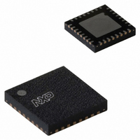
SC68C752BIBS,157 NXP Semiconductors, SC68C752BIBS,157 Datasheet - Page 27

SC68C752BIBS,157
Manufacturer Part Number
SC68C752BIBS,157
Description
IC UART DUAL 32HVQFN
Manufacturer
NXP Semiconductors
Datasheet
1.SC68C752BIBS128.pdf
(48 pages)
Specifications of SC68C752BIBS,157
Number Of Channels
2, DUART
Fifo's
64 Byte
Voltage - Supply
2.5V, 3.3V, 5V
With Auto Flow Control
Yes
With False Start Bit Detection
Yes
With Modem Control
Yes
Mounting Type
Surface Mount
Package / Case
32-VFQFN Exposed Pad
Lead Free Status / RoHS Status
Lead free / RoHS Compliant
Other names
935280969157
SC68C752BIBS
SC68C752BIBS
SC68C752BIBS
SC68C752BIBS
NXP Semiconductors
SC68C752B_4
Product data sheet
7.8 Interrupt Enable Register (IER)
The Interrupt Enable Register (IER) enables each of the six types of interrupt, receiver
error, RHR interrupt, THR interrupt, Xoff received, or CTSn/RTSn change of state from
LOW to HIGH. The IRQ output signal is activated in response to interrupt generation.
Table 17
Table 17.
[1]
Bit
7
6
5
4
3
2
1
0
IER[7:4] can only be modified if EFR[4] is set, that is, EFR[4] is a write enable. Re-enabling IER[1] will not
cause a new interrupt if the THR is below the threshold.
Symbol
IER[7]
IER[6]
IER[5]
IER[4]
IER[3]
IER[2]
IER[1]
IER[0]
shows Interrupt Enable Register bit settings.
Interrupt Enable Register bits description
[1]
[1]
[1]
[1]
Description
CTS interrupt enable.
RTS interrupt enable.
Xoff interrupt.
Sleep mode.
Modem Status Interrupt.
Receive Line Status interrupt.
Transmit Holding Register interrupt.
Receive Holding Register interrupt.
5 V, 3.3 V and 2.5 V dual UART, 5 Mbit/s (max.), with 64-byte FIFOs
logic 0 = disable the CTS interrupt (normal default condition)
logic 1 = enable the CTS interrupt
logic 0 = disable the RTS interrupt (normal default condition)
logic 1 = enable the RTS interrupt
logic 0 = disable the Xoff interrupt (normal default condition)
logic 1 = enable the Xoff interrupt
logic 0 = disable Sleep mode (normal default condition)
logic 1 = enable Sleep mode. See
logic 0 = disable the Modem Status Register interrupt (normal default
condition)
logic 1 = enable the Modem Status Register interrupt
logic 0 = disable the receiver line status interrupt (normal default condition)
logic 1 = enable the receiver line status interrupt
logic 0 = disable the THR interrupt (normal default condition)
logic 1 = enable the THR interrupt
logic 0 = disable the RHR interrupt (normal default condition)
logic 1 = enable the RHR interrupt
Rev. 04 — 20 January 2010
Section 6.7 “Sleep mode”
SC68C752B
© NXP B.V. 2010. All rights reserved.
for details.
27 of 48


