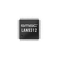
LAN9312-NZW SMSC, LAN9312-NZW Datasheet - Page 393

LAN9312-NZW
Manufacturer Part Number
LAN9312-NZW
Description
Ethernet ICs Hi Per 2 Port 10/100 Ethernet Switch
Manufacturer
SMSC
Type
Two Port Managed Ethernet Switchr
Datasheet
1.LAN9312-NZW.pdf
(458 pages)
Specifications of LAN9312-NZW
Ethernet Connection Type
10 Base-T, 100 Base-TX
Minimum Operating Temperature
0 C
Mounting Style
SMD/SMT
Product
Ethernet Switches
Number Of Transceivers
1
Standard Supported
802.3, 802.3u
Data Rate
10 Mbps, 100 Mbps
Supply Voltage (max)
3.3 V
Supply Voltage (min)
0 V
Supply Current (max)
186 mA, 295 mA
Maximum Operating Temperature
+ 70 C
Package / Case
TQFP-100
Lead Free Status / RoHS Status
Lead free / RoHS Compliant
Available stocks
Company
Part Number
Manufacturer
Quantity
Price
Company:
Part Number:
LAN9312-NZW
Manufacturer:
Standard
Quantity:
143
Company:
Part Number:
LAN9312-NZW
Manufacturer:
Microchip Technology
Quantity:
10 000
- Current page: 393 of 458
- Download datasheet (5Mb)
High Performance Two Port 10/100 Managed Ethernet Switch with 32-Bit Non-PCI CPU Interface
Datasheet
SMSC LAN9312
14.5.3.26
BITS
31:8
6:5
4:0
7
RESERVED
Ingress Rate RnW
These bits specify a read(1) or write(0) command.
Type
These bits select between the ingress rate metering/color table registers as
follows:
00 = RESERVED
01 = Committed Information Rate Registers
10 = Committed Burst Register
11 = Excess Burst Register
CIR Address
These bits select one of the 24 Committed Information Rate registers.
When Rate Mode is set to Source Port & Priority in the
Ingress Rate Configuration Register
set of 8 registers (CIR addresses 0-7) are for to Port 0, the second set of 8
registers (CIR addresses 8-15) are for Port 1, and the third set of registers
(CIR addresses 16-23) are for Port 2. Priority 0 is the lower register of each
set (e.g. 0, 8, and 16).
When Rate Mode is set to Source Port Only, the first register (CIR address
0) is for Port 0, the second register (CIR address 1) is for Port 1, and the
third register (CIR address 2) is for Port 2.
When Rate Mode is set to Priority Only, the first register (CIR address 0) is
for priority 0, the second register (CIR address 1) is for priority 1, and so
forth up to priority 23.
Note:
Switch Engine Ingress Rate Command Register (SWE_INGRSS_RATE_CMD)
This register is used to indirectly read and write the ingress rate metering/color table registers. A write
to this address performs the specified access.
For a read access, the Operation Pending bit in the
Register (SWE_INGRSS_RATE_CMD_STS)
Engine Ingress Rate Read Data Register (SWE_INGRSS_RATE_RD_DATA)
F o r a w r i t e a c c e s s , t h e
(SWE_INGRSS_RATE_WR_DATA)
Engine Ingress Rate Command Status Register (SWE_INGRSS_RATE_CMD_STS)
command is finished.
For details on 16-bit wide Ingress Rate Table registers indirectly accessible by this register, see
Section 14.5.3.26.1
Values outside of the valid range may cause unexpected results.
Register #:
below.
184Bh
DESCRIPTION
(SWE_INGRSS_RATE_CFG), the first
DATASHEET
S w i t c h E n g i n e I n g r e s s R a t e W r i t e D a t a R e g i s t e r
should be written first. The Operation Pending bit in the
393
(uses CIS Address field)
indicates when the command is finished. The
Size:
Switch Engine
Switch Engine Ingress Rate Command Status
32 bits
TYPE
can then be read.
R/W
R/W
R/W
RO
Revision 1.7 (06-29-10)
indicates when the
DEFAULT
00b
0b
0h
-
Switch
Switch
Related parts for LAN9312-NZW
Image
Part Number
Description
Manufacturer
Datasheet
Request
R

Part Number:
Description:
Ethernet ICs Hi Per 2 Port 10/100 Ethernet Switch
Manufacturer:
SMSC
Datasheet:

Part Number:
Description:
FAST ETHERNET PHYSICAL LAYER DEVICE
Manufacturer:
SMSC Corporation
Datasheet:

Part Number:
Description:
357-036-542-201 CARDEDGE 36POS DL .156 BLK LOPRO
Manufacturer:
SMSC Corporation
Datasheet:

Part Number:
Description:
357-036-542-201 CARDEDGE 36POS DL .156 BLK LOPRO
Manufacturer:
SMSC Corporation
Datasheet:

Part Number:
Description:
357-036-542-201 CARDEDGE 36POS DL .156 BLK LOPRO
Manufacturer:
SMSC Corporation
Datasheet:

Part Number:
Description:
4-PORT USB2.0 HUB CONTROLLER
Manufacturer:
SMSC Corporation
Datasheet:

Part Number:
Description:
Manufacturer:
SMSC Corporation
Datasheet:

Part Number:
Description:
Manufacturer:
SMSC Corporation
Datasheet:

Part Number:
Description:
FDC37C672ENHANCED SUPER I/O CONTROLLER WITH FAST IR
Manufacturer:
SMSC Corporation
Datasheet:

Part Number:
Description:
COM90C66LJPARCNET Controller/Transceiver with AT Interface and On-Chip RAM
Manufacturer:
SMSC Corporation
Datasheet:

Part Number:
Description:
Manufacturer:
SMSC Corporation
Datasheet:

Part Number:
Description:
Manufacturer:
SMSC Corporation
Datasheet:

Part Number:
Description:
Manufacturer:
SMSC Corporation
Datasheet:

Part Number:
Description:
Manufacturer:
SMSC Corporation
Datasheet:


