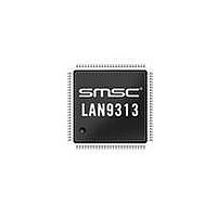
LAN9313I-NZW SMSC, LAN9313I-NZW Datasheet - Page 51

LAN9313I-NZW
Manufacturer Part Number
LAN9313I-NZW
Description
Ethernet ICs Three Port 10/100 Ethernet Switch
Manufacturer
SMSC
Type
Three Port Managed Ethernet Switchr
Datasheet
1.LAN9313-NZW.pdf
(399 pages)
Specifications of LAN9313I-NZW
Ethernet Connection Type
10 Base-T, 100 Base-TX
Minimum Operating Temperature
0 C
Mounting Style
SMD/SMT
Product
Ethernet Switches
Number Of Transceivers
1
Standard Supported
802.3, 802.3u
Data Rate
10 Mbps, 100 Mbps
Supply Voltage (max)
3.3 V
Supply Voltage (min)
0 V
Supply Current (max)
155 mA, 270 mA
Maximum Operating Temperature
+ 70 C
Package / Case
TQFP-100
Lead Free Status / RoHS Status
Lead free / RoHS Compliant
Available stocks
Company
Part Number
Manufacturer
Quantity
Price
Company:
Part Number:
LAN9313I-NZW
Manufacturer:
Standard
Quantity:
261
Company:
Part Number:
LAN9313I-NZW
Manufacturer:
Microchip Technology
Quantity:
10 000
- Current page: 51 of 399
- Download datasheet (5Mb)
Three Port 10/100 Managed Ethernet Switch with MII
Datasheet
SMSC LAN9313/LAN9313i
4.3
4.3.1
eeprom_size_strap[1:0]
MII_mode_strap
phy_addr_sel_strap
STRAP NAME
The LAN9313/LAN9313i Port 1 and Port 2 PHYs support several power management and wakeup
features.
Port 1 & 2 PHY Power Management
The Port 1 & 2 PHYs provide independent general power-down and energy-detect power-down modes
which reduce PHY power consumption. General power-down mode provides power savings by
powering down the entire PHY, except the PHY management control interface. General power-down
mode must be manually enabled and disabled as described in
Down," on page
In energy-detect power-down mode, the PHY will resume from power-down when energy is seen on
the cable (typically from link pulses). If the ENERGYON interrupt (INT7) of either PHYs
Interrupt Mask Register (PHY_INTERRUPT_MASK_x)
generate an interrupt. These interrupts are reflected in the
(PHY_INT2) for the Port 2 PHY, and bit 26 (PHY_INT1) for the Port 1 PHY. These interrupts can be
used to trigger the IRQ interrupt output pin, as described in
on page
operation and configuration of the PHY energy-detect power-down mode.
Power Management
55. Refer to
Table 4.3 Hard-Strap Configuration Strap Definitions
97.
EEPROM Size Strap [1:0]: Configures the EEPROM size
range as specified in
EEPROM Controller," on page
MII Mode Strap: Configures the default mode of the
external MII port.
0 = MAC Mode
1 = PHY Mode
Refer to
additional information on the various modes of the
LAN9313/LAN9313i.
PHY Address Select Strap: Configures the default MII
management address values for the PHYs and Virtual PHY
as detailed in
Section 7.2.9.2, "PHY Energy Detect Power-Down," on page 97
0
1
Section 2.3, "Modes of Operation," on page 23
0
1
Section 7.1.1, "PHY Addressing," on page
DATASHEET
1
2
Section 8.2, "I2C/Microwire Master
DESCRIPTION
51
2
3
101.
is unmasked, then the corresponding PHY will
Interrupt Status Register (INT_STS)
Section 5.2.3, "Ethernet PHY Interrupts,"
Section 7.2.9.1, "PHY General Power-
for
84.
EEPROM_SIZE_[1:0]
MII_MODE
PHY_ADDR_SEL
Revision 1.7 (06-29-10)
for details on the
PIN
Port x PHY
bit 27
Related parts for LAN9313I-NZW
Image
Part Number
Description
Manufacturer
Datasheet
Request
R

Part Number:
Description:
Three Port 10/100 Managed Ethernet Switch with MII
Manufacturer:
SMSC [SMSC Corporation]
Datasheet:

Part Number:
Description:
Ethernet ICs Three Port 10/100 Ethernet Switch
Manufacturer:
SMSC
Datasheet:

Part Number:
Description:
Ethernet ICs Three Port 10/100 Ethernet Switch
Manufacturer:
SMSC
Datasheet:

Part Number:
Description:
FAST ETHERNET PHYSICAL LAYER DEVICE
Manufacturer:
SMSC Corporation
Datasheet:

Part Number:
Description:
357-036-542-201 CARDEDGE 36POS DL .156 BLK LOPRO
Manufacturer:
SMSC Corporation
Datasheet:

Part Number:
Description:
357-036-542-201 CARDEDGE 36POS DL .156 BLK LOPRO
Manufacturer:
SMSC Corporation
Datasheet:

Part Number:
Description:
357-036-542-201 CARDEDGE 36POS DL .156 BLK LOPRO
Manufacturer:
SMSC Corporation
Datasheet:

Part Number:
Description:
4-PORT USB2.0 HUB CONTROLLER
Manufacturer:
SMSC Corporation
Datasheet:

Part Number:
Description:
Manufacturer:
SMSC Corporation
Datasheet:

Part Number:
Description:
Manufacturer:
SMSC Corporation
Datasheet:

Part Number:
Description:
FDC37C672ENHANCED SUPER I/O CONTROLLER WITH FAST IR
Manufacturer:
SMSC Corporation
Datasheet:

Part Number:
Description:
COM90C66LJPARCNET Controller/Transceiver with AT Interface and On-Chip RAM
Manufacturer:
SMSC Corporation
Datasheet:

Part Number:
Description:
Manufacturer:
SMSC Corporation
Datasheet:

Part Number:
Description:
Manufacturer:
SMSC Corporation
Datasheet:


