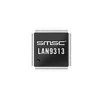
LAN9313I-NZW SMSC, LAN9313I-NZW Datasheet - Page 153

LAN9313I-NZW
Manufacturer Part Number
LAN9313I-NZW
Description
Ethernet ICs Three Port 10/100 Ethernet Switch
Manufacturer
SMSC
Type
Three Port Managed Ethernet Switchr
Datasheet
1.LAN9313-NZW.pdf
(399 pages)
Specifications of LAN9313I-NZW
Ethernet Connection Type
10 Base-T, 100 Base-TX
Minimum Operating Temperature
0 C
Mounting Style
SMD/SMT
Product
Ethernet Switches
Number Of Transceivers
1
Standard Supported
802.3, 802.3u
Data Rate
10 Mbps, 100 Mbps
Supply Voltage (max)
3.3 V
Supply Voltage (min)
0 V
Supply Current (max)
155 mA, 270 mA
Maximum Operating Temperature
+ 70 C
Package / Case
TQFP-100
Lead Free Status / RoHS Status
Lead free / RoHS Compliant
Available stocks
Company
Part Number
Manufacturer
Quantity
Price
Company:
Part Number:
LAN9313I-NZW
Manufacturer:
Standard
Quantity:
261
Company:
Part Number:
LAN9313I-NZW
Manufacturer:
Microchip Technology
Quantity:
10 000
- Current page: 153 of 399
- Download datasheet (5Mb)
Three Port 10/100 Managed Ethernet Switch with MII
Datasheet
SMSC LAN9313/LAN9313i
13.1.1.2
25:20
18:13
BITS
11:0
31
30
29
28
27
26
19
12
Software Interrupt (SW_INT)
This interrupt is generated when the SW_INT_EN bit of the
Register (INT_EN)
Device Ready (READY)
This interrupt indicates that the LAN9313/LAN9313i is ready to be
accessed after a power-up or reset condition.
1588 Interrupt Event (1588_EVNT)
This bit indicates an interrupt event from the IEEE 1588 module. This bit
should be used in conjunction with the
Register (1588_INT_STS_EN)
event within the 1588 module.
Switch Fabric Interrupt Event (SWITCH_INT)
This bit indicates an interrupt event from the Switch Fabric. This bit should
be used in conjunction with the
(SW_IPR)
Fabric.
Port 2 PHY Interrupt Event (PHY_INT2)
This bit indicates an interrupt event from the Port 2 PHY. The source of the
interrupt can be determined by polling the
Flags Register
Port 1 PHY Interrupt Event (PHY_INT1)
This bit indicates an interrupt event from the Port 1 PHY. The source of the
interrupt can be determined by polling the
Flags Register
RESERVED
GP Timer (GPT_INT)
This interrupt is issued when the
(GPT_CNT)
RESERVED
GPIO Interrupt Event (GPIO)
This bit indicates an interrupt event from the General Purpose I/O. The
source of the interrupt can be determined by polling the
I/O Interrupt Status and Enable Register (GPIO_INT_STS_EN)
RESERVED
Interrupt Status Register (INT_STS)
This register contains the current status of the generated interrupts. A value of 1 indicates the
corresponding interrupt conditions have been met, while a value of 0 indicates the interrupt conditions
have not been met. The bits of this register reflect the status of the interrupt source regardless of
whether the source has been enabled as an interrupt in the
indicated as R/WC, writing a 1 to the corresponding bits acknowledges and clears the interrupt.
to determine the source of the interrupt event within the Switch
Offset:
wraps past zero to FFFFh.
(PHY_INTERRUPT_SOURCE_x).
(PHY_INTERRUPT_SOURCE_x).
is set high. Writing a one clears this interrupt.
058h
DESCRIPTION
to determine the source of the interrupt
Switch Global Interrupt Pending Register
General Purpose Timer Count Register
DATASHEET
1588 Interrupt Status and Enable
Port x PHY Interrupt Source
Port x PHY Interrupt Source
153
Size:
General Purpose
Interrupt Enable
Interrupt Enable Register
32 bits
R/WC
R/WC
R/WC
TYPE
RO
RO
RO
RO
RO
RO
RO
RO
Revision 1.7 (06-29-10)
(INT_EN). Where
DEFAULT
0b
0b
0b
0b
0b
0b
0b
0b
-
-
-
Related parts for LAN9313I-NZW
Image
Part Number
Description
Manufacturer
Datasheet
Request
R

Part Number:
Description:
Three Port 10/100 Managed Ethernet Switch with MII
Manufacturer:
SMSC [SMSC Corporation]
Datasheet:

Part Number:
Description:
Ethernet ICs Three Port 10/100 Ethernet Switch
Manufacturer:
SMSC
Datasheet:

Part Number:
Description:
Ethernet ICs Three Port 10/100 Ethernet Switch
Manufacturer:
SMSC
Datasheet:

Part Number:
Description:
FAST ETHERNET PHYSICAL LAYER DEVICE
Manufacturer:
SMSC Corporation
Datasheet:

Part Number:
Description:
357-036-542-201 CARDEDGE 36POS DL .156 BLK LOPRO
Manufacturer:
SMSC Corporation
Datasheet:

Part Number:
Description:
357-036-542-201 CARDEDGE 36POS DL .156 BLK LOPRO
Manufacturer:
SMSC Corporation
Datasheet:

Part Number:
Description:
357-036-542-201 CARDEDGE 36POS DL .156 BLK LOPRO
Manufacturer:
SMSC Corporation
Datasheet:

Part Number:
Description:
4-PORT USB2.0 HUB CONTROLLER
Manufacturer:
SMSC Corporation
Datasheet:

Part Number:
Description:
Manufacturer:
SMSC Corporation
Datasheet:

Part Number:
Description:
Manufacturer:
SMSC Corporation
Datasheet:

Part Number:
Description:
FDC37C672ENHANCED SUPER I/O CONTROLLER WITH FAST IR
Manufacturer:
SMSC Corporation
Datasheet:

Part Number:
Description:
COM90C66LJPARCNET Controller/Transceiver with AT Interface and On-Chip RAM
Manufacturer:
SMSC Corporation
Datasheet:

Part Number:
Description:
Manufacturer:
SMSC Corporation
Datasheet:

Part Number:
Description:
Manufacturer:
SMSC Corporation
Datasheet:


