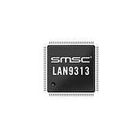
LAN9313I-NZW SMSC, LAN9313I-NZW Datasheet - Page 45

LAN9313I-NZW
Manufacturer Part Number
LAN9313I-NZW
Description
Ethernet ICs Three Port 10/100 Ethernet Switch
Manufacturer
SMSC
Type
Three Port Managed Ethernet Switchr
Datasheet
1.LAN9313-NZW.pdf
(399 pages)
Specifications of LAN9313I-NZW
Ethernet Connection Type
10 Base-T, 100 Base-TX
Minimum Operating Temperature
0 C
Mounting Style
SMD/SMT
Product
Ethernet Switches
Number Of Transceivers
1
Standard Supported
802.3, 802.3u
Data Rate
10 Mbps, 100 Mbps
Supply Voltage (max)
3.3 V
Supply Voltage (min)
0 V
Supply Current (max)
155 mA, 270 mA
Maximum Operating Temperature
+ 70 C
Package / Case
TQFP-100
Lead Free Status / RoHS Status
Lead free / RoHS Compliant
Available stocks
Company
Part Number
Manufacturer
Quantity
Price
Company:
Part Number:
LAN9313I-NZW
Manufacturer:
Standard
Quantity:
261
Company:
Part Number:
LAN9313I-NZW
Manufacturer:
Microchip Technology
Quantity:
10 000
- Current page: 45 of 399
- Download datasheet (5Mb)
Three Port 10/100 Managed Ethernet Switch with MII
Datasheet
SMSC LAN9313/LAN9313i
4.2.4
4.2.4.1
STRAP NAME
LED_en_strap[7:0]
LED_fun_strap[1:0]
Configuration Straps
Configuration straps allow various features of the LAN9313/LAN9313i to be automatically configured
to user defined values. Configuration straps can be organized into two main categories: hard-straps
and soft-straps. Both hard-straps and soft-straps are latched upon Power-On Reset (POR) or pin reset
(nRST). The primary difference between these strap types is that soft-strap default values can be
overridden by the EEPROM Loader, while hard-straps cannot.
Configuration straps which have a corresponding external pin include internal resistors in order to
prevent the signal from floating when unconnected. If a particular configuration strap is connected to
a load, an external pull-up or pull-down resistor should be used to augment the internal resistor to
ensure that it reaches the required voltage level prior to latching. The internal resistor can also be
overridden by the addition of an external resistor.
Note: The system designer must guarantee that configuration strap pins meet the timing
Soft-Straps
Soft-strap values are latched on the release of POR or nRST and are overridden by values from the
EEPROM Loader (when an EEPROM is present). These straps are used as direct configuration values
or as defaults for CPU registers. Some, but not all, soft-straps have an associated pin. Those that do
not have an associated pin, have a tie off default value. All soft-strap values can be overridden by the
EEPROM Loader.
Straps which have an associated pin are also fully defined in
Configuration," on page
the operation of the EEPROM Loader and the loading of strap values.
Upon setting the DIGITAL_RST bit in the
RELOAD command via the
original latched (non-overridden) values if an EEPROM is no longer attached or has been erased. The
associated pins are not re-sampled. (i.e. The value latched on the pin during the last POR or nRST
will be used, not the value on the pin during the digital reset or RELOAD command issuance). If it is
desired to re-latch the current configuration strap pin values, a POR or nRST must be issued.
requirements specified in
If configuration strap pins are not at the correct voltage level prior to being latched, the
LAN9313/LAN9313i may capture incorrect strap values.
Table 4.2 Soft-Strap Configuration Strap Definitions
Table 4.2
DESCRIPTION
LED Enable Straps: Configures the default value for the
LED_EN bits in the
(LED_CFG). A high value configures the associated
LED/GPIO pin as a LED. A low value configures the
associated LED/GPIO pin as a GPIO.
Note:
LED Function Straps: Configures the default value for the
LED_FUN bits in the
(LED_CFG). When configured low, the corresponding bit
will be cleared. When configured high, the corresponding
bit will be set.
26. Refer to
One pin configures the default for all 8
LED/GPIOs, but 8 separate bits are loaded by the
EEPROM Loader, allowing individual control over
each LED/GPIO.
provides a list of all soft-straps and their associated pin or default value.
EEPROM Command Register
Section 14.5.2, "Reset and Configuration Strap Timing," on page
DATASHEET
Section 8.2.4, "EEPROM Loader," on page 113
LED Configuration Register
LED Configuration Register
45
Reset Control Register (RESET_CTL)
(E2P_CMD), these straps return to their
Chapter 3, "Pin Description and
PIN / DEFAULT
VALUE
LED_EN
LED_FUN[1:0]
Revision 1.7 (06-29-10)
or upon issuing a
for information on
389.
Related parts for LAN9313I-NZW
Image
Part Number
Description
Manufacturer
Datasheet
Request
R

Part Number:
Description:
Three Port 10/100 Managed Ethernet Switch with MII
Manufacturer:
SMSC [SMSC Corporation]
Datasheet:

Part Number:
Description:
Ethernet ICs Three Port 10/100 Ethernet Switch
Manufacturer:
SMSC
Datasheet:

Part Number:
Description:
Ethernet ICs Three Port 10/100 Ethernet Switch
Manufacturer:
SMSC
Datasheet:

Part Number:
Description:
FAST ETHERNET PHYSICAL LAYER DEVICE
Manufacturer:
SMSC Corporation
Datasheet:

Part Number:
Description:
357-036-542-201 CARDEDGE 36POS DL .156 BLK LOPRO
Manufacturer:
SMSC Corporation
Datasheet:

Part Number:
Description:
357-036-542-201 CARDEDGE 36POS DL .156 BLK LOPRO
Manufacturer:
SMSC Corporation
Datasheet:

Part Number:
Description:
357-036-542-201 CARDEDGE 36POS DL .156 BLK LOPRO
Manufacturer:
SMSC Corporation
Datasheet:

Part Number:
Description:
4-PORT USB2.0 HUB CONTROLLER
Manufacturer:
SMSC Corporation
Datasheet:

Part Number:
Description:
Manufacturer:
SMSC Corporation
Datasheet:

Part Number:
Description:
Manufacturer:
SMSC Corporation
Datasheet:

Part Number:
Description:
FDC37C672ENHANCED SUPER I/O CONTROLLER WITH FAST IR
Manufacturer:
SMSC Corporation
Datasheet:

Part Number:
Description:
COM90C66LJPARCNET Controller/Transceiver with AT Interface and On-Chip RAM
Manufacturer:
SMSC Corporation
Datasheet:

Part Number:
Description:
Manufacturer:
SMSC Corporation
Datasheet:

Part Number:
Description:
Manufacturer:
SMSC Corporation
Datasheet:


