D4BL-1DRA-A Omron, D4BL-1DRA-A Datasheet - Page 13
D4BL-1DRA-A
Manufacturer Part Number
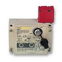
D4BL-1DRA-A
Description
SAFETY SWITCH
Manufacturer
Omron
Specifications of D4BL-1DRA-A
Contact Voltage Ac Max
250V
Contact Voltage Dc Max
250V
Contact Current Ac Max
30A
Contact Current Dc Max
300mA
Switch Terminals
Screw
Svhc
No SVHC (15-Dec-2010)
Approval Bodies
EN60947-5-1, IEC 947-5-1, EN1088,
Lead Free Status / Rohs Status
Lead free / RoHS Compliant


H
The head can be mounted in four directions. To remove the head,
turn the head by 45 as shown in figures A and B below.
To change the direction of the head, make sure that the protruding
part of the rotating lever engages with the groove of the plunger.
Then turn the head clockwise or counterclockwise to the desired
direction. At that time, make sure that the groove of the plunger is
located under the rotating lever. If the direction of the head is not set
when the plunger is rotated by 45 , the groove of the plunger pres-
H
Be sure to check the mechanical lock and solenoid release func-
tions when mounting the D4BL.
If the head direction is changed, recheck the tightening torque of
each of screw. Make sure that no foreign materials will penetrate
through the key hole on the head.
ses the rotating lever. The head, plunger, or the built-in switch may
be damaged as a result.
D4BL
HEAD DIRECTIONS
HEAD DIRECTION CHANGES
Normal Positions of Rotating Lever and Plunger
Front
Head Bottom View
Operation plunger and
groove mechanism
(45 )
Left
Switch body
(A)
(B)
Switch Top View
Built-in switch
Rotating lever (with
protruding part)
Plunger (with groove)
Rotation lever and
protruding part
Right
(45 )
Back
H
The dedicated release key, which is provided with the D4BL, is used
to unlock the protective door in case of emergency or power failure.
To open the protective door, insert the dedicated release key and set
the key lock to UNLOCK.
If the key lock is set to UNLOCK, when the protective door is closed
and people are doing preparation work on the machine inside, the
protective door will not be locked and the machine will not start
operating.
Use the release key to set the key lock to LOCK.
Do not use the release key to start or stop the machine.
This key lock must be normally set to LOCK and sealed with a rub-
ber cap in order to conform to IP67 requirements.
The dedicated release key should be kept only by the person in
charge.
If necessary, to prevent easy access to the dedicated release key,
seal the key lock using a suitable sealing wax. Be careful not to dam-
age the key lock when breaking the seal between the rubber cap
and the key lock.
A cover can be attached to the D4BL. Before attaching the cover,
make sure that the key lock is set to LOCK.
H
The D4BL is provided with a shock absorptive damper when
shipped attached to the D4BL in order to prevent the D4BL from be-
ing damaged if it is dropped accidentally. Be sure to remove the
shock absorptive damper after the D4BL is mounted.
Do not impose excessive force to the Operation Key in the switch or
drop the Operation Key, or the Operation Key may be deformed or
damaged.
Do not operate the Safety-door Lock Switch with a tool other than
OMRON’s special Operation Key for the Safety-door Lock Switch,
otherwise the Safety-door Lock Switch may be damaged or the
safety of the system will not be assured.
DEDICATED RELEASE KEY
OPERATION KEY
UNLOCK
LOCK
Dropping
Release key
D4BL
13
Related parts for D4BL-1DRA-A
Image
Part Number
Description
Manufacturer
Datasheet
Request
R

Part Number:
Description:
Contact OSTI For Purchase
Manufacturer:
Omron
Datasheet:

Part Number:
Description:
Safety Switch
Manufacturer:
Omron
Datasheet:
Part Number:
Description:
Locking Solenoid Safety Switch
Manufacturer:
Omron
Datasheet:
Part Number:
Description:
Interlock Switch
Manufacturer:
Omron
Datasheet:
Part Number:
Description:
G1/2,1NC/1NO,mch Lck,110v Rel.
Manufacturer:
Omron
Datasheet:
Part Number:
Description:
Solenoid Interlock Switch
Manufacturer:
Omron
Datasheet:
Part Number:
Description:
Solenoid Interlock Switch
Manufacturer:
Omron
Datasheet:
Part Number:
Description:
SOLENOID INTERLOCK SWITCH
Manufacturer:
Omron
Datasheet:
Part Number:
Description:
Contact OSTI For Purchase
Manufacturer:
Omron
Datasheet:

Part Number:
Description:
Contact OSTI For Purchase
Manufacturer:
Omron
Datasheet:
Part Number:
Description:
LIMIT SWITCH ADJ ROLL LEVER
Manufacturer:
Omron
Datasheet: