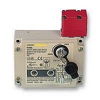
D4BL-1DRA-A Omron, D4BL-1DRA-A Datasheet

D4BL-1DRA-A
Specifications of D4BL-1DRA-A
Related parts for D4BL-1DRA-A
D4BL-1DRA-A Summary of contents
Page 1
... Canada Tel. 1/888/510-4357 on A: Mechanical lock/24-VDC solenoid release B: Mechanical lock/110-VAC solenoid release G: 24-VDC Solenoid lock/Mechanical release Blank: Without indicator A: For the Latest Information Tel. 1/866/986-6766 On the Internet: www.sti.com or www.omron. 115 VAC or VDC driving (with orange and green LED indicator unit) AA-75 ...
Page 2
... D4BL-3CRG-A TÜV Rheinland BIA SUVA UL CSA CQC (CCC) Ask your OMRON representative for information on approved models. For the Latest Information Tel. 1/866/986-6766 On the Internet: www.sti.com or www.omron.ca D4BL-1DRA D4BL-1DRA-A D4BL-1DRB D4BL-1DRB-A D4BL-2DRA D4BL-2DRA-A D4BL-2DRB D4BL-2DRB-A D4BL-3DRA D4BL-3DRA-A D4BL-3DRB D4BL-3DRB-A D4BL-1DRG D4BL-1DRG-A D4BL-2DRG ...
Page 3
... Although the switch box is protected from dust, oil or water penetration, do not use the D4BL in places where dust, oil, water, or chemicals may enter through the key hole on the head, otherwise Switch damage or malfunctioning may occur. ...
Page 4
... D4BL Guard Lock Safety-door Switch 24 VDC Approx. 300 mA Class F (130 C or less) D4BL-@C@@-@ 1NC/1NO+1NC 31 D4BL-@D@@-@ 2NC+1NC 31 The EN-approved direct opening mechanism is indicated by (Safety circuit side) (Monitor circuit side) Four terminal plates Two, 7 dia. (7) (16) 26.8 53.2 57.2 (16) 0.3 5.6 (35) 26.2 (61.2) OMRON SCIENTIFIC TECHNOLOGIES, INC ...
Page 5
... E1 (+) Auxiliary circuit (monitor circuit) E1 (+) Auxiliary circuit (monitor circuit) For the Latest Information On the Internet: www.sti.com or www.omron.ca D4BL Guard Lock Safety-door Switch (Power supply side) E1 (+) 31 32 Solenoid LED (orange) LED (green) (Ground side) Safety circuit (Power supply side) E1 (+) 31 32 Solenoid LED (orange) ...
Page 6
... D4BL Guard Lock Safety-door Switch @ Lock release signal KM1 KM2 Guard S1 OPEN Stop signal A1 A2 T11 T21 Limit switch S1 Guard Lock Safety-door Switch S2 Lock release signal Lock release switch S4 Stop signal Reset switch S3 K1 and K2 (NC) K1 and K2 (NO) K3 and K4 (NC) K3 and K4 ...
Page 7
... Motor controller Guard opens KM1 KM2 S1: Safety Limit Switch with direct opening mechanism (D4B-N, D4N, D4F) S2: Guard Lock Safety-door Switch KM1 and KM2: Magnetic Contactor M: 3-phase motor For the Latest Information On the Internet: www.sti.com or www.omron.ca Guard Lock Safety-door Switch M D4BL AA-81 ...
Page 8
... D4BL Guard Lock Safety-door Switch @ @@ @ Auxiliary release key Lock monitor switch Solenoid Conduit opening Connection Ground terminal M3.5 (Pull out terminal M3.5 horizontally) The head can be changed to any of four directions. OMRON SCIENTIFIC TECHNOLOGIES, INC. USA Canada Tel. 1/888/510-4357 AA- Operation Key Lock plate ...
Page 9
... Guard Lock Safety-door Switch 31 37.5 Lock protection cap Four, 5.3 dia. mounting holes +1 86 Four cover clamping screws Cover 16 5.5 39.6 Conduit opening 31 37.5 Four, 5.3 dia. Mounting holes +1 86 Four cover clamping screws Cover 5.5 16 Conduit opening 39.6 42.6 D4BL AA-83 ...
Page 10
... D4BL Guard Lock Safety-door Switch Red 40.7 25.8 15.6 36 11.8 5.6 4 dia. Red 40 Red 30 5.3 dia. OMRON SCIENTIFIC TECHNOLOGIES, INC. USA Canada Tel. 1/888/510-4357 AA-84 78.7 20 0.15 Long mounting hole 12 7.3 15 Two, 2.65R 5.3 5.3 7.5 2 25.8 15.6 (80.7) 36 2.6 11.8 19 ...
Page 11
... Horizontal direction Operation Key insertion radius R 250 81.5 min. 85 max. (41) (40) (30 0.15) For the Latest Information On the Internet: www.sti.com or www.omron.ca D4BL Guard Lock Safety-door Switch Vertical direction Operation Key insertion radius R 1000 (20 0.15) (35) Vertical direction Operation Key insertion radius R ...
Page 12
... Always attach the cover after completing wiring and before using the Switch. Electric shock may occur if the Switch is used without the cover attached. Connect a fuse in series with the D4BL in series to protect it from short-circuit damage. The value of the breaking current of the fuse must be calculated by multiplying the rated current by 150% to 200%. ...
Page 13
... Observe the specified insertion radius for the Operation Key and insert direction perpendicular to the key hole. Four, M5 The Operation Key for the D4BL is different from the one for the D4BS. The head can be mounted in four directions. To remove the head, turn the head shown in figures (A) and (B) below. ...
Page 14
... Properly attach and securely tighten the provided conduit cap to the unused conduit opening when wiring the D4BL. ALL DIMENSIONS SHOWN ARE IN MILLIMETERS. To convert millimeters into inches, multiply by 0.03937. To convert grams into ounces, multiply by 0.03527. In the interest of product improvement, specifications are subject to change without notice. ...


