D4BL-1DRA-A Omron, D4BL-1DRA-A Datasheet - Page 11
D4BL-1DRA-A
Manufacturer Part Number
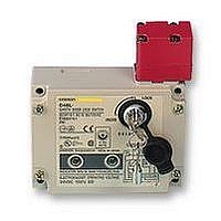
D4BL-1DRA-A
Description
SAFETY SWITCH
Manufacturer
Omron
Specifications of D4BL-1DRA-A
Contact Voltage Ac Max
250V
Contact Voltage Dc Max
250V
Contact Current Ac Max
30A
Contact Current Dc Max
300mA
Switch Terminals
Screw
Svhc
No SVHC (15-Dec-2010)
Approval Bodies
EN60947-5-1, IEC 947-5-1, EN1088,
Lead Free Status / Rohs Status
Lead free / RoHS Compliant


Installation
H
The following procedure is recommended so that the D4BL can be
wired or connected to the Indicator Units with ease.
Recommended connecting cable:
AWB20 to AWG18 with seven conductors
A UL2464-style cable is recommended.
Apply sealing tape to the cable and conduit opening so that the
D4BL can conform to IP67. Tighten the connector to a torque of 1.8
to 2.2 NSm (15.93 to 19.47 in lbs).
Connect the Indicator Units to the D4BL after connecting the 7-con-
ductor cable to the D4BL.
Terminal no.
E
E
31
12
23 (21)
24 (22)
Ground
D4BL
1
2
PROCEDURE FOR CONNECTING CABLE
Lp mm (inch)
30 2
(1.18 0.08)
35 2
(1.38 0.08)
45 2
(1.77 0.08)
55 2
(2.17 0.08)
65 2
(2.56 0.08)
70 2
(2.76 0.08)
90 2
(3.54 0.08)
Lp
Lv mm (inch)
80 2
(3.15 0.08)
75 2
(2.95 0.08)
60 2
(2.36 0.08)
50 2
(1.97 0.08)
45 2
(1.77 0.08)
35 2
(1.38 0.08)
50 2
(1.9 0.087)
a
Lv
a
a mm (inch)
8 1
(0.31 0.08)
Cable Connecting Example
The wire leads must be wrapped around the screws clockwise.
Tighten each screw to a torque of 0.5 to 0.7 NSm (4.43 to 6.20 in lbs).
1. As shown in the following illustration, the wires must be
2. The external insulation sheath of the 7-conductor cable must
connected in sequence beginning with the terminal nearest to
the conduit opening.
contact with side A or B as shown in the above D4BL
illustration.
Edge of insulation sheath
A
E
1
E
2
31 12 23 24
B
D4BL
11
Related parts for D4BL-1DRA-A
Image
Part Number
Description
Manufacturer
Datasheet
Request
R

Part Number:
Description:
Contact OSTI For Purchase
Manufacturer:
Omron
Datasheet:

Part Number:
Description:
Safety Switch
Manufacturer:
Omron
Datasheet:
Part Number:
Description:
Locking Solenoid Safety Switch
Manufacturer:
Omron
Datasheet:
Part Number:
Description:
Interlock Switch
Manufacturer:
Omron
Datasheet:
Part Number:
Description:
G1/2,1NC/1NO,mch Lck,110v Rel.
Manufacturer:
Omron
Datasheet:
Part Number:
Description:
Solenoid Interlock Switch
Manufacturer:
Omron
Datasheet:
Part Number:
Description:
Solenoid Interlock Switch
Manufacturer:
Omron
Datasheet:
Part Number:
Description:
SOLENOID INTERLOCK SWITCH
Manufacturer:
Omron
Datasheet:
Part Number:
Description:
Contact OSTI For Purchase
Manufacturer:
Omron
Datasheet:

Part Number:
Description:
Contact OSTI For Purchase
Manufacturer:
Omron
Datasheet:
Part Number:
Description:
LIMIT SWITCH ADJ ROLL LEVER
Manufacturer:
Omron
Datasheet: