D4BL-K3 Omron, D4BL-K3 Datasheet
D4BL-K3
Specifications of D4BL-K3


Related parts for D4BL-K3

D4BL-K3 Summary of contents
Page 1
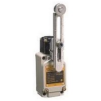
... D4BL Locking Safety-Door Switch Protective Doors Are Locked Until Machines Completely Stop Operating The switch contact is opened by a positive H opening mechanism (NC contacts only). Positive opening mechanism that is EN-approved is indicated by switch Auxiliary release key ensures easy H maintenance and unlocks the door in the ...
Page 2
... American type) 2. Built-in Switch C: 1NC/1NO (Slow-action) + 1NC (Slow-action) D: 2NC (Slow-action) + 1NC (Slow-action) 3. Head Mounting Direction R: Mounting possible in 4 directions (mounted in the right direction at time of delivery) Operation Key (Order Separately) D4BL - Operation Key Type 1: Horizontal mounting 2: Vertical mounting 3: Adjustable mounting (Horizontal) ...
Page 3
... D4BL J OPERATION KEY (ORDER SEPARATELY) Mounting type Part number Horizontal mounting D4BL-K1 Vertical mounting D4BL-K2 Adjustable mounting D4BL-K3 (Horizontal) Specifications J APPROVED STANDARD RATINGS TÜV (EN60947-5-1) Item Standard model Utilization category AC-15 Rated operating current (Ie Rated operating voltage (Ue) 250 V As protection against short-circuiting, use either a gI-type or gG-type 10-A fuse (IEC269-approved). ...
Page 4
... Current consumption Approx Indicator color (LED) Orange, green ) 4 kV (EN60947-5-1) between terminals of different polarity, imp 2 min. (IEC68-2-27) 2 min. (IEC68-2-27) 110-VAC Mechanical lock models / (100% ED) 110 VAC ±10% (50/60 Hz) --15% Approx D4BL 2 24-VAC Solenoid lock models +10% 24 VDC / (100% ED) --15% Approx. 300 mA ...
Page 5
... SHOW STATE WITH KEY INSERTED AND LOCK ENGAGED) Model Contact D4BL-jCjj-j 1NC/1NO+1NC 31 D4BL-jDjj-j 2NC+1NC 31 Note: The EN-approved positive opening mechanism is indicated by D4BL-jDjj-j Operation Key Lock plate Auxiliary release key Rotating drum Lock monitor switch Solenoid Operation plunger Seal ring (NBR) Auxiliary plunger ...
Page 6
... Recommended Circuit Connection Example 1. Connect the crimp-style terminals of each indicator unit to the internal terminals (terminals 31 and 12, 23 and 24, and 21 and 22) of the D4BL. 2. Each indicator unit must be connected in parallel with the contacts. When the contacts are open, the indicators will be lit. ...
Page 7
... D4BL J OPERATING MODE (Example of Electromagnetic Interlock System Operating Mode of D4BL-jCjA-A) Operating I II mode Door The protective door is The protective door is open. closed. Door Operation Key: The Operation Key: Mechanically locked mechanical lock is switch (contacts 31 and 32 are released (contacts 31 ON). and 32 are OFF). ...
Page 8
... Note: A tolerance of ±0.4 mm applies to all dimensions unless otherwise specified. J SWITCHES D4BL-jjjj-j Red J OPERATION KEYS Horizontal Mounting D4BL-K1 Red 78.7 20±0.15 40.7 25.8 15.6 5.3 5.3 36 11.8 5.6 4 dia. Adjustable Mounting (Horizontal) D4BL-K3 Red 40 30±0.15 Red 30 5.3 dia. 116.5 15 34.2 123.5 74±0.1 6.8 100±0.1 Conduit opening +1 112 0 ...
Page 9
... J WITH OPERATION KEY INSERTED Horizontal Mounting D4BL + D4BL-K1 Red 53.5 min. 57 max. Vertical Mounting D4BL + D4BL-K2 Red 54.5 min. 58 max. Adjustable Mounting (Horizontal) D4BL + D4BL-K3 Red Horizontal direction Operation Key insertion radius R ≧ 1200 (side view) 53.5 min. 57 max. 20±0. Horizontal direction Operation Key insertion radius R ≧ ...
Page 10
... PC output (Stop signal) E-SW Note: Wire terminal 11 and terminal 22 on G9S to the PC output common. S1: D4DN or D4BN Safety-door Lock Switch S2: D4BL Guard Lock Safety-door Lock Switch with solenoid lock S3: Reset switch KM1, KM2: J7K Magnet Contactor M: 3-phase motor E-SW: Emergency stop switch (A22E) ...
Page 11
... PC output (Stop signal) E-SW Note: Wire terminal 11 and terminal 22 on G9S to the PC output common. S1: Safety Switch (D4D-j520N) S2: D4BL Guard Lock Safety-door Lock Switch with mechanical lock S3: Push-button switch for solenoid KM1, KM2: Magnet Contactor (LC1-D) M: 3-phase motor E-SW: Emergency-stop switch (A22E) ...
Page 12
... J CORRECT USE Operating Environment Due to the wear and tear of the sealing of the D4BL, water and some types of oil and chemical sprayed onto the D4BL may cause contact or insulation failures, current leakages, or fires. Do Not Use the D4BL in the Following Places Places with radical temperature changes. • ...
Page 13
... The D4BL may break soon if the door opens accidentally or a space is present between the set zone of the Key and the D4BL as shown below. This may be due to the weight of the door, vibration of the machine, or bouncing of the door against the rubber bumper. Be sure to apply appropriate parts, such as hooks, so that no such space will exist ...
Page 14
... Vertical Mounting D4BL-K2 Two, M5 40±0.1 Adjustable Mounting (Horizontal) D4BL-K3 Two, M5 30±0.1 Head Directions The head can be mounted in four directions. To remove the head, turn the head by 45° as shown in figures A and B below. To change the direction of the head, make sure that the protruding part of the rotating lever engages with the groove of the plunger ...
Page 15
... Terminal no. Lp (mm) Lv (mm) E 30±2 80± 35±2 75± 45±2 60±2 12 55±2 50±2 23 (21) 65±2 45±2 24 (22) 70±2 35±2 90±2 50±2 Properly attach and securely tighten the provided conduit cap to the unused conduit opening when wiring the D4BL (mm) 8±1 ...
Page 16
... A or side B. Maintenance and Repairs Contact your OMRON representative for any repair or maintenance work on the D4BL. The D4BL must not be maintained or repaired by any unauthorized party. Using the D4BL Do not touch the solenoid because the solenoid radiates heat while power is being supplied ...