D4BL-1DRA-A Omron, D4BL-1DRA-A Datasheet - Page 12
D4BL-1DRA-A
Manufacturer Part Number
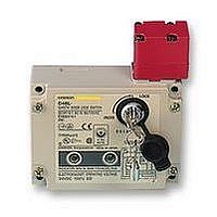
D4BL-1DRA-A
Description
SAFETY SWITCH
Manufacturer
Omron
Specifications of D4BL-1DRA-A
Contact Voltage Ac Max
250V
Contact Voltage Dc Max
250V
Contact Current Ac Max
30A
Contact Current Dc Max
300mA
Switch Terminals
Screw
Svhc
No SVHC (15-Dec-2010)
Approval Bodies
EN60947-5-1, IEC 947-5-1, EN1088,
Lead Free Status / Rohs Status
Lead free / RoHS Compliant


Precautions
H
Be sure to install a stopper as shown in the following illustration
when mounting the Safety-door Lock Switch. The range of space “a”
must be determined according to the available set zone 4 mm (0.16
inch) max. of the Operation Key.
Refer to Dimensions for the mounting dimensions of the Operation
Key to mount the Operation Key correctly. The Operation Key will
quickly become damaged or worn away if it is not mounted correctly.
12
D4BL
MOUNTING
Operation key
Set zone mark
Switch
a
Stopper
Switch Mounting Holes
Operation Key Mounting Holes
Proper Mounting Screw Tightening Torque
Conduit
1.8 to 2.2 NSm
(15.93 to 19.47 in lbs)
Two, M5 operation key clamping screws 2.4
to 2.8 NSm (21.24 to 24.78 in lbs)
Four, M4 cover clamping
screws 1.2 to 1.4 NSm (10.62
to 12.39 in lbs)
D4BL-K1
D4BL-K2
D4BL-K3
74 (2.91)
Four, M5
Unit mounting screws
4.9 to 5.9 NSm (43.37
to 52.22 in lbs)
100 (3.94)
20 (0.79)
40 (1.57)
30 (1.18)
Four, M3.5 head clamping screws
0.8 to 1.0 NSm (7.08 to 8.85 in lbs)
Conduit opening cap
1.3 to 1.7 NSm (11.51
to 11.51 in lbs)
Two, M5
Four, M5
Two, M5
Two, M5
D4BL
Related parts for D4BL-1DRA-A
Image
Part Number
Description
Manufacturer
Datasheet
Request
R

Part Number:
Description:
Contact OSTI For Purchase
Manufacturer:
Omron
Datasheet:

Part Number:
Description:
Safety Switch
Manufacturer:
Omron
Datasheet:
Part Number:
Description:
Locking Solenoid Safety Switch
Manufacturer:
Omron
Datasheet:
Part Number:
Description:
Interlock Switch
Manufacturer:
Omron
Datasheet:
Part Number:
Description:
G1/2,1NC/1NO,mch Lck,110v Rel.
Manufacturer:
Omron
Datasheet:
Part Number:
Description:
Solenoid Interlock Switch
Manufacturer:
Omron
Datasheet:
Part Number:
Description:
Solenoid Interlock Switch
Manufacturer:
Omron
Datasheet:
Part Number:
Description:
SOLENOID INTERLOCK SWITCH
Manufacturer:
Omron
Datasheet:
Part Number:
Description:
Contact OSTI For Purchase
Manufacturer:
Omron
Datasheet:

Part Number:
Description:
Contact OSTI For Purchase
Manufacturer:
Omron
Datasheet:
Part Number:
Description:
LIMIT SWITCH ADJ ROLL LEVER
Manufacturer:
Omron
Datasheet: