D4BL-1DRA-A Omron, D4BL-1DRA-A Datasheet
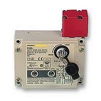
D4BL-1DRA-A
Specifications of D4BL-1DRA-A


Related parts for D4BL-1DRA-A


D4BL-1DRA-A Summary of contents
Page 1
... Note: Contact your sales representative for details on models with safety standard certification. Be sure to read the “Safety Precautions” on page 13 and the “Precautions for All Safety Door Switches”. Operation Key D4BL - Operation Key Type 1: Horizontal mounting 2: Vertical mounting 3: Adjustable mounting (Horizontal) ...
Page 2
... D4BL-4CRG D4BL-4CRG-A Model D4BL-K1 D4BL-K2 D4BL-K3 D4BL 1 : Models with certified direct opening contacts. Without indicator With LED indicator 2NC+ 1NC 2NC+ 1NC (Slow-action) (Slow-action) D4BL-1DRA D4BL-1DRA-A D4BL-1DRB D4BL-1DRB-A D4BL-2DRA D4BL-2DRA-A D4BL-2DRB D4BL-2DRB-A D4BL-3DRA D4BL-3DRA-A D4BL-3DRB D4BL-3DRB-A D4BL-4DRA D4BL-4DRA-A D4BL-4DRB D4BL-4DRB-A D4BL-1DRG ...
Page 3
... Note: The UL/CSA certified rating for products with indicators (- A/115 VAC. Certified Standards Certification body EN60947-5-1 (certified direct TÜV Rheinland opening) GS-ET-19 UL UL508 CSA CSA C22.2, No.14 CQC (CCC) GB14048.5 Indicator model AC- 115 V Current (A) Make Break D4BL Standard File No. R9451050 E76675 LR45746 2003010305073836 Volt-amperes (VA) Make Break 7,200 720 3 ...
Page 4
... The degree of protection is tested using the method specified by the standard (EN60947-5-1). Confirm that sealing properties are sufficient for the operating conditions and environment beforehand. Although the switch box is protected from dust, oil or water penetration, do not use the D4BL in places where dust, oil, water, or chemicals may enter through the key hole on the head, otherwise Switch damage or malfunctioning may occur. ...
Page 5
... Lock monitor and lock monitor) Lock monitor D4BL-@C@@-@ 1NC/1NO+1NC 31 Lock monitor D4BL-@D@@-@ 2NC+1NC 31 Note: The EN-certified direct opening mechanism is indicated by Contact Form (D4BL-2GRD-AT) (Safety circuit side) (Monitor circuit side) D4BL-@D@@-@ Operation Key Lock plate Auxiliary release key Rotating drum Lock monitor switch ...
Page 6
... N max. Key extraction force 19.61 N max. Movement before 15 mm max. being locked Total travel 23 mm min. 37.5 Operating Model +1 D4BL-2GRD-AT 86 Characteristics 0 Key insertion force 19.61 N max. Key extraction force 19.61 N max. Movement before 15 mm max. being locked Total travel 23 mm min. ...
Page 7
... D4BL-K3 78.7 20 Long mounting hole 12 7.3 15 Two, 2.65R 5.3 5.3 7.5 2 5.3 x 7.3 long mounting hole 40 52.4 5.3 11.9 7.5 5.3 dia. 20 2.6 D4BL Red Red ° 26 15.6 18 ° (80. 2.6 11.8 19.5 5 dia. 17.5 34.6 M4 Allen-head bolt (37.8) ...
Page 8
... R ≥ 1200 54.5 min. 58 max. (13) (41) (40±0.15) Vertical direction Operation Key insertion radius R ≥ 1000 54.5 min. 58 max. (41) (35) D4BL D4BL + D4BL-K3 Red Horizontal direction Operation Key insertion radius R ≥ 250 81.5 min. 85 max. (41) (40) (30±0.15) Vertical direction Operation Key insertion radius R ≥ ...
Page 9
... Indicator Unit Four terminal plates Two, 7 dia. Two LED (7) (16) 26.8 53.2 57.2 (16) 0.3 5.6 (35) 26.2 (61.2) Connections Internal Circuit Diagram Indicator 10 to 115 VAC/VDC Constant-current diode 2 10.6 (12.6) Solenoid 24 VDC E1 (+) LED E2 (−) D4BL 9 ...
Page 10
... E2 (− Auxiliary circuit (monitor circuit) 4. Orange: Lights when the solenoid turns ON. Green: Lights when power turns ON. E1 (+) (− Auxiliary circuit (monitor circuit) D4BL (Power supply side) E1 (+) 32 31 Solenoid E2 (−) LED (orange) LED (green) Safety circuit (Power supply side) E1 (+) 32 31 Solenoid E2 (−) ...
Page 11
... Connection Example with OMRON’s G9SA Safety Relay Unit G9SA-321-T@ (24 VAC/VDC) + D4BL-@D@A-@, -@D@B-@ (Mechanical Lock Type) Circuit Diagram (Manual Reset) Lock release signal KM1 KM2 PLC Guard S1 OPEN Stop signal A1 A2 T11 T12 T21 Timing Chart Limit switch S1 Guard Lock ...
Page 12
... G9SA-301 (24 VAC/VDC) + D4BL-@D@G-@ (Solenoid Lock Type) Circuit Diagram (Auto-reset) Lock signal PLC 12 OPEN 11 Operation signal A1 A2 T11 T12 T21 T23 T22 Timing Chart Limit switch S1 Guard Lock Safety-door Switch S2 Operation signal Lock signal K1 and K2 (NC) K1 and K2 (NO) KM1 and KM2 ...
Page 13
... Four, M5 switch-mounting screw Auxiliary Release Key • The auxiliary release key is used to unlock the D4BL in case of emergency or in case the power supply to the D4BL fails. • Use the enclosed Release Key to change the lock from LOCK to UNLOCK so that the lock will be released and the door can be opened ...
Page 14
... D4BL-K3 Two, M5 30±0.1 Operation Key • The D4BL is provided with a shock-absorbing damper to protect the D4BL from damage that may result from dropping the D4BL during transportation. Be sure to remove the damper after mounting the D4BL. • The mounting tolerance of the Operation Key is ±0.3 mm vertically or horizontally ...
Page 15
... Properly attach and securely tighten the provided conduit cap to the unused conduit opening to the suitable tightening torque when wiring the D4BL. Cable Connection Example 1. Connect the wires to the terminals in the order shown below for wiring efficiency. Tighten each wired terminal clockwise to a torque of 0.59 to 0.78 N· ...
Page 16
... Please read and understand this catalog before purchasing the products. Please consult your OMRON representative if you have any questions or comments. WARRANTY OMRON's exclusive warranty is that the products are free from defects in materials and workmanship for a period of one year (or other period if specified) from date of sale by OMRON. OMRON MAKES NO WARRANTY OR REPRESENTATION, EXPRESS OR IMPLIED, REGARDING NON-INFRINGEMENT, MERCHANTABILITY, OR FITNESS FOR PARTICULAR PURPOSE OF THE PRODUCTS ...