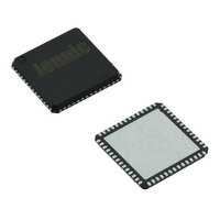
JN5148-001-X NXP Semiconductors, JN5148-001-X Datasheet - Page 92

JN5148-001-X
Manufacturer Part Number
JN5148-001-X
Description
IC MCU 802.15.4 32BIT 2.4G 56QFN
Manufacturer
NXP Semiconductors
Series
JN5148r
Datasheet
1.JN5148-UG010.pdf
(99 pages)
Specifications of JN5148-001-X
Frequency
2.4GHz
Data Rate - Maximum
667kbps
Modulation Or Protocol
802.15.4
Applications
Home/Building Automation, Industrial Control
Power - Output
2.5dBm
Sensitivity
-95dBm
Voltage - Supply
2 V ~ 3.6 V
Current - Receiving
17.5mA
Current - Transmitting
15mA
Data Interface
PCB, Surface Mount
Memory Size
128kB RAM, 128kB ROM
Antenna Connector
PCB, Surface Mount
Operating Temperature
-40°C ~ 85°C
Package / Case
56-QFN
Lead Free Status / RoHS Status
Lead free / RoHS Compliant
Other names
616-1049-2
935293999531
JN5148-001-X
935293999531
JN5148-001-X
B.3 32kHz Oscillator
In order to obtain more accurate sleep periods, the JN5148 contains the necessary on-chip components to build an
optional 32kHz oscillator with the addition of an external 32.768kHz crystal and two tuning capacitors. The crystal
should be connected between XTAL32K_IN and XTAL32K_OUT (DIO9 and DIO10), with two equal capacitors to
ground, one on each pin. The schematic of these components are shown in Figure 58. The two capacitors, C1 and
C2, will typically be in the range 10 to 22pF ±5% and use a COG dielectric. As with all crystal oscillators the PCB
layout is especially important, both to keep parasitic capacitors to a minimum and to reduce the possibility of PCB
noise being coupled into the oscillator.
The electrical specification of the oscillator can be found in 22.3.12. The oscillator cell is flexible and can operate with
a range of commonly available 32kHz crystals with load capacitances from 6 to 12.5p, and ESR up to 80KΩ. It
achieves this by using automatic gain control (AGC), which senses the signal swing. As explained in Appendix B.1.3
there is a trade-off that exists between the load capacitance and crystal ESR to achieve reliable performance. The
use of an AGC function allows a wider range of crystal load capacitors and ESR’s to be accommodated than would
otherwise be possible. However, this benefit does mean the supply current varies with the supply voltage (VDD),
value of the total capacitance at each pin, and the crystal ESR. This is described in the table and graphs below.
32kHz Crystal Requirements
92
Crystal Frequency
Supply Current
Supply Current Temp. Coeff.
Crystal ESR Range (Rm)
Crystal Load Capacitance
Range (CL)
Parameter
Not all Combinations of Crystal Load Capacitance and ESR are Valid
XTAL32K_IN
Figure 58: 32kHz crystal oscillator connections
10KΩ
Min
6pF
JN-DS-JN5148-001 1v6
0.1%/ C
32kHz
1.6uA
25KΩ
Typ
9pF
XTAL32K_OUT
JN5148
12.5pF
80KΩ
Max
© NXP Laboratories UK 2010
Vdd=3v, temp=25 C, load
cap =9pF, Rm=25K
Vdd=3v
See below for more details
See below for more details
Notes


