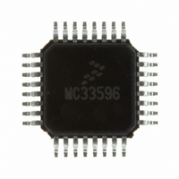
MC33596FJE Freescale Semiconductor, MC33596FJE Datasheet - Page 28

MC33596FJE
Manufacturer Part Number
MC33596FJE
Description
IC RECEIVER UHF PLL TUNED 32LQFP
Manufacturer
Freescale Semiconductor
Type
Receiverr
Datasheet
1.MC33596FCAE.pdf
(70 pages)
Specifications of MC33596FJE
Frequency
304, 315, 426, 434, 868 & 915MHz
Sensitivity
-104dBm
Data Rate - Maximum
22.4 kBaud
Modulation Or Protocol
FSK, OOK
Applications
General Data Transfer
Current - Receiving
10.3mA
Data Interface
PCB, Surface Mount
Antenna Connector
PCB, Surface Mount
Voltage - Supply
2.7 V ~ 3.6 V, 4.5 V ~ 5.5 V
Operating Temperature
-40°C ~ 85°C
Package / Case
32-LQFP
Operating Frequency
915 MHz
Operating Supply Voltage
3.3 V or 5 V
Maximum Operating Temperature
+ 85 C
Minimum Operating Temperature
- 40 C
Mounting Style
SMD/SMT
Operating Temperature (min)
-40C
Operating Temperature (max)
85C
Operating Temperature Classification
Industrial
Modulation Type
FSK/OOK
Package Type
LQFP
Operating Supply Voltage (min)
2.7V
Lead Free Status / RoHS Status
Lead free / RoHS Compliant
Features
-
Memory Size
-
Lead Free Status / Rohs Status
Lead free / RoHS Compliant
Available stocks
Company
Part Number
Manufacturer
Quantity
Price
Part Number:
MC33596FJE
Manufacturer:
FREESCALE
Quantity:
20 000
Part Number:
MC33596FJER2
Manufacturer:
FREESCALE
Quantity:
20 000
Power-On Reset and MC33596 Startup
Figure 22
mode.
14
The startup sequence can be divided into three stages as defined in
28
STROBE
CONFB
STROBE
STROBE
CONFB
CONFB
SEB
SEB
SCLK
SCLK
MOSI
MOSI
1. MC33596 is in receive mode.
2. CONFB is forced to low level during one digital period T
3. CONFB is set to high level during the time length of an ID.
1. The power supply is applied to the MC33596 and an external pullup resistor on CONFB is required
SEB
only.
to enter standby mode. SEB can be either set to low level if the SPI access is not shared with
another external MCU, or connected to an external pullup resistor (see
Interface”).
During this stage and during the ramp-up of the power supply, signals from the MCU connected to
the MC33596 are undefined. That is why the MC33596 must start in standby mode.
— Power supply of the MC33596 must rise in 1 ms from 0 V to 3 V.
— The level on STROBE pin is lower than 0.75 V until the power supply reaches 3 V.
Power-On Reset and MC33596 Startup
describes the sequence for enabling a correct transition from receive mode to configuration
Along with the ramp-up of power supply, one of these two conditions must
be complied with:
Figure 21. Valid Sequence from Standby/LVD Mode to Configuration Mode
SPI Startup Time
Figure 22. Valid Sequence from Receive Mode to Configuration Mode
1
1
2
2
3
3
MC33596 Data Sheet, Rev. 4
NOTE
digclk
Figure
in order to reset the state machine
23:
Section 9, “MCU
Freescale Semiconductor


