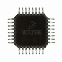
MC33596FJE Freescale Semiconductor, MC33596FJE Datasheet - Page 17

MC33596FJE
Manufacturer Part Number
MC33596FJE
Description
IC RECEIVER UHF PLL TUNED 32LQFP
Manufacturer
Freescale Semiconductor
Type
Receiverr
Datasheet
1.MC33596FCAE.pdf
(70 pages)
Specifications of MC33596FJE
Frequency
304, 315, 426, 434, 868 & 915MHz
Sensitivity
-104dBm
Data Rate - Maximum
22.4 kBaud
Modulation Or Protocol
FSK, OOK
Applications
General Data Transfer
Current - Receiving
10.3mA
Data Interface
PCB, Surface Mount
Antenna Connector
PCB, Surface Mount
Voltage - Supply
2.7 V ~ 3.6 V, 4.5 V ~ 5.5 V
Operating Temperature
-40°C ~ 85°C
Package / Case
32-LQFP
Operating Frequency
915 MHz
Operating Supply Voltage
3.3 V or 5 V
Maximum Operating Temperature
+ 85 C
Minimum Operating Temperature
- 40 C
Mounting Style
SMD/SMT
Operating Temperature (min)
-40C
Operating Temperature (max)
85C
Operating Temperature Classification
Industrial
Modulation Type
FSK/OOK
Package Type
LQFP
Operating Supply Voltage (min)
2.7V
Lead Free Status / RoHS Status
Lead free / RoHS Compliant
Features
-
Memory Size
-
Lead Free Status / Rohs Status
Lead free / RoHS Compliant
Available stocks
Company
Part Number
Manufacturer
Quantity
Price
Part Number:
MC33596FJE
Manufacturer:
FREESCALE
Quantity:
20 000
Part Number:
MC33596FJER2
Manufacturer:
FREESCALE
Quantity:
20 000
11.2.3.3 HEADER
The HEADER defines the beginning of the message, as it is compared with the HEADER register. Its
length is variable, defined by the HDL[1:0] bits. The complement of the header is also recognized as the
header—in this case, output data is complemented. The header and its complement should not be part of
the ID.
The ID and the header are sent at the same data rate as data.
11.2.3.4 Data and EOM
The data must follow the header, with no delay.
The message is completed with an end-of-message (EOM), consisting of two consecutive NRZ ones or
zeroes (i.e., a Manchester code violation). Even in the case of FSK modulation, data must conclude with
an EOM, and not simply by stopping the RF transmission.
11.2.4 State Machine in Receive Mode When DME=1
When the strobe oscillator is enabled (SOE = 1), the receiver is continuously cycling on/off. The ID must
be recognized for the receiver to stay on. Consequently, the transmitted ID burst must be long enough to
include two consecutive receiver-on cycles.
When the strobe oscillator is not enabled (SOE = 0), these timing constraints must be respected by the
external control applied to pin STROBE.
Figure 11
oscillator (SOE=1) or externally by the MCU (SOE=0).
Two different processes are possible, as determined by the values of the SOE bit.
11.2.4.1 Data Manager Enabled and Strobe Oscillator Enabled
Figure 11
configuration, the receiver is controlled internally by the strobe oscillator. However, external control via
the STROBE pin is still possible, and overrides the strobe oscillator command.
Freescale Semiconductor
Receiver
Receiver
Output
Output
Signal
Signal
Status
Status
SPI
SPI
RF
RF
shows the correct detection of an ID when STROBE is controled internally using the strobe
shows the state diagram when the data manager and the strobe oscillator are enabled. In this
On Time
On Time
On
On
Preamble
Preamble
Figure 10. Complete Transmission with ID Detection
ID
ID
Off Time
Off Time
ID
ID
Off
Off
ID
ID
MC33596 Data Sheet, Rev. 4
ID Field
ID Field
ID
ID
ID
ID
Detected
Detected
ID
ID
ID
ID
ID
ID
Header
Header
On
On
Data
Data
Data
Data
EOM
EOM
Receive Mode
Off
Off
17


