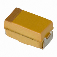
TAJA225K006RNJ AVX Corporation, TAJA225K006RNJ Datasheet - Page 20

TAJA225K006RNJ
Manufacturer Part Number
TAJA225K006RNJ
Description
CAP TANT 2.2UF 6.3V 10% SMD
Manufacturer
AVX Corporation
Series
TAJr
Type
Moldedr
Specifications of TAJA225K006RNJ
Capacitance
2.2µF
Package / Case
1206 (3216 Metric)
Voltage - Rated
6.3V
Tolerance
±10%
Operating Temperature
-55°C ~ 125°C
Mounting Type
Surface Mount
Size / Dimension
0.126" L x 0.063" W (3.20mm x 1.60mm)
Height
0.063" (1.60mm)
Manufacturer Size Code
A
Features
General Purpose
Tolerance (+ Or -)
10%
Voltage
6.3VDC
Esr
9Ohm
Mounting Style
Surface Mount
Polarity
Polar
Construction
SMT Chip
Case Style
Molded
Case Code
A
Lead Spacing (nom)
Not Requiredmm
Df
6%
Dcl
0.5uA
Seal
Not Required
Insulation
Not Required
Failure Rate
Not Required
Wire Form
Not Required
Product Length (mm)
3.2mm
Product Height (mm)
1.6mm
Product Depth (mm)
1.6mm
Product Diameter (mm)
Not Requiredmm
Seated Plane Height
Not Requiredmm
Length W/weld (max)
Not Requiredmm
Operating Temp Range
-55C to 125C
Lead Free Status / RoHS Status
Lead free / RoHS Compliant
Lead Spacing
-
Esr (equivalent Series Resistance)
-
Lead Free Status / RoHS Status
Compliant, Lead free / RoHS Compliant
Other names
TAJA225K006R
TAJA225K006R
TAJA225K006R
Technical Summary and
Application Guidelines
SECTION 5
MECHANICAL AND THERMAL PROPERTIES OF CAPACITORS
5.1 Acceleration
5.2 Vibration Severity
5.3 Shock
5.4 Adhesion to Substrate
5.5 Resistance to Substrate Bending
5.6 Soldering Conditions
5.7 Installation Instructions
5.8 Installation Position
5.9 Soldering Instructions
5.9.1 Guidelines for Surface Mount Footprints
The component footprint is defined as the maximum board
area taken up by the terminators. The footprint dimensions
are given by A, B, C and D in the diagram, which corre-
sponds to W, max., A max., S min. and L max. for the com-
ponent. The footprint is symmetric about the center lines.
The dimensions x, y and z should be kept to a minimum
to reduce rotational tendencies while allowing for visual
inspection of the component and its solder fillet.
48
98.1m/s
10 to 2000Hz, 0.75mm of 98.1m/s
Trapezoidal Pulse, 98.1m/s
IEC 384-3. minimum of 5N.
No restriction.
Fluxes containing acids must not be used.
The component has compliant leads which reduces
the risk of stress on the capacitor due to substrate
bending.
Dip soldering is permissible provided the solder bath
temperature is
and the circuit board thickness
The upper temperature limit (maximum capacitor surface
temperature) must not be exceeded even under the
most unfavorable conditions when the capacitor is
installed. This must be considered particularly when it
is positioned near components which radiate heat
strongly
Furthermore, care must be taken, when bending
the wires, that the bending forces do not strain the
capacitor housing.
Component footprint and reflow pad design for AVX
capacitors.
PW
2
(10g)
(e.g.
PL
270°C, the solder time < 3 seconds
valves
PSL
PS
D
C
z
2
and
for 6ms.
B
1.0mm.
power
2
(10g)
Y
A
x
transistors).
PAD DIMENSIONS:
Dimensions PS (Pad Separation) and PW (Pad Width) are
calculated using dimensions x and z. Dimension y may
vary, depending on whether reflow or wave soldering is to
be performed.
For reflow soldering, dimensions PL (Pad Length), PW (Pad
Width), and PSL (Pad Set Length) have been calculated. For
wave soldering the pad width (PWw) is reduced to less than
the termination width to minimize the amount of solder pick
up while ensuring that a good joint can be produced.
NOTE: These recommendations (also in compliance with EIA) are guidelines
Nominal footprint and pad dimensions for each case size are
given in the following tables:
5.10 PCB Cleaning
If aqueous cleaning is performed, parts must be allowed
to dry prior to test. In the event ultrasonics are used power
levels should be less than 10 watts per/litre, and care must
be taken to avoid vibrational nodes in the cleaning bath.
SECTION 6
EPOXY FLAMMABILITY
SECTION 7
QUALIFICATION APPROVAL STATUS
CASE
TAJ
TAC
TAZ
DESCRIPTION
Surface mount
capacitors
Ta chip capacitors are compatible with most PCB board
cleaning systems.
EPOXY
only. With care and control, smaller footprints may be considered for
reflow soldering.
W
G
A
B
C
D
V
E
R
S
T
Y
R
A
B
D
E
H
L
F
TPS
TAZ
THJ
TAJ
4.0 (0.157)
4.0 (0.157)
6.5 (0.256)
8.0 (0.315)
8.3 (0.325)
8.0 (0.315)
2.7 (0.100)
4.0 (0.160)
4.0 (0.160)
6.5 (0.256)
8.0 (0.315)
2.4 (0.095)
3.0 (0.120)
3.3 (0.126)
4.5 (0.178)
4.5 (0.178)
5.8 (0.228)
6.3 (0.248)
7.4 (0.293)
8.0 (0.313)
PSL
STYLE
1.4 (0.054)
1.4 (0.054)
2.0 (0.079)
2.0 (0.079)
2.3 (0.090)
2.0 (0.079)
1.0 (0.040)
1.4 (0.050)
1.4 (0.050)
2.0 (0.079)
2.0 (0.079)
0.7 (0.027)
0.7 (0.027)
1.4 (0.054)
1.4 (0.054)
1.4 (0.054)
1.4 (0.054)
1.4 (0.054)
1.9 (0.074)
1.9 (0.074)
TAZ
TAJ
UL RATING
PL
UL94 V-0
UL94 V-0
UL94 V-0
UL94 V-0
millimeters (inches)
1.2 (0.047)
1.2 (0.047)
2.5 (0.098)
4.0 (0.157)
3.7 (0.145)
4.0 (0.157)
1.0 (0.040)
1.0 (0.040)
1.0 (0.040)
2.5 (0.098)
4.0 (0.157)
0.9 (0.035)
1.6 (0.063)
0.5 (0.020)
1.8 (0.070)
1.8 (0.070)
3.0 (0.120)
3.6 (0.140)
3.7 (0.145)
4.2 (0.165)
SPECIFICATION
CECC 30801 - 005 Issue 2
CECC 30801 - 011 Issue 1
MIL-C-55365/8 (CWR11)
MIL-C-55365/4 (CWR09)
PS
1.8 (0.071)
2.8 (0.110)
2.8 (0.110)
3.0 (0.119)
3.7 (0.145)
3.0 (0.119)
1.6 (0.060)
1.8 (0.070)
2.8 (0.110)
2.8 (0.110)
3.0 (0.119)
1.0 (0.039)
1.5 (0.059)
2.5 (0.098)
2.5 (0.098)
3.6 (0.143)
3.6 (0.143)
4.5 (0.178)
4.0 (0.157)
5.0 (0.197)
OXYGEN INDEX
PW
35%
35%
35%
35%
0.9 (0.035)
1.6 (0.063)
1.6 (0.063)
1.7 (0.068)
1.7 (0.068)
1.7 (0.068)
0.8 (0.030)
0.8 (0.030)
0.8 (0.030)
1.6 (0.063)
1.7 (0.068)
1.0 (0.039)
1.0 (0.039)
2.0 (0.079)
2.2 (0.085)
3.0 (0.119)
2.4 (0.095)
3.4 (0.135)
PWw
-
-


