TAJA225K006RNJ AVX Corporation, TAJA225K006RNJ Datasheet - Page 12
TAJA225K006RNJ
Manufacturer Part Number
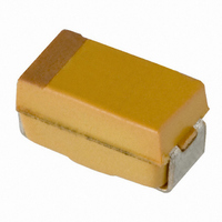
TAJA225K006RNJ
Description
CAP TANT 2.2UF 6.3V 10% SMD
Manufacturer
AVX Corporation
Series
TAJr
Type
Moldedr
Specifications of TAJA225K006RNJ
Capacitance
2.2µF
Package / Case
1206 (3216 Metric)
Voltage - Rated
6.3V
Tolerance
±10%
Operating Temperature
-55°C ~ 125°C
Mounting Type
Surface Mount
Size / Dimension
0.126" L x 0.063" W (3.20mm x 1.60mm)
Height
0.063" (1.60mm)
Manufacturer Size Code
A
Features
General Purpose
Tolerance (+ Or -)
10%
Voltage
6.3VDC
Esr
9Ohm
Mounting Style
Surface Mount
Polarity
Polar
Construction
SMT Chip
Case Style
Molded
Case Code
A
Lead Spacing (nom)
Not Requiredmm
Df
6%
Dcl
0.5uA
Seal
Not Required
Insulation
Not Required
Failure Rate
Not Required
Wire Form
Not Required
Product Length (mm)
3.2mm
Product Height (mm)
1.6mm
Product Depth (mm)
1.6mm
Product Diameter (mm)
Not Requiredmm
Seated Plane Height
Not Requiredmm
Length W/weld (max)
Not Requiredmm
Operating Temp Range
-55C to 125C
Lead Free Status / RoHS Status
Lead free / RoHS Compliant
Lead Spacing
-
Esr (equivalent Series Resistance)
-
Lead Free Status / RoHS Status
Compliant, Lead free / RoHS Compliant
Other names
TAJA225K006R
TAJA225K006R
TAJA225K006R


Technical Summary and
Application Guidelines
1.4.4 Temperature dependence of the Impedance
At 100kHz, impedance and ESR behave identically and
decrease with increasing temperature as the typical curves
show.
1.5 D.C. LEAKAGE CURRENT
1.5.1 Leakage current.
The leakage current is dependent on the voltage applied,
the elapsed time since the voltage was applied and the
component temperature. It is measured at +20°C with the
rated voltage applied. A protective resistance of 1000
is connected in series with the capacitor in the measuring
circuit. Three to five minutes after application of the rated
voltage the leakage current must not exceed the maximum
values indicated in the ratings table. These are based on the
formulae 0.01CV or 0.5µA (whichever is the greater).
Reforming of tantalum capacitors is unnecessary even after
prolonged storage periods without the application of voltage.
1.5.2 Temperature dependence of the leakage
The leakage current increases with higher temperatures,
typical values are shown in the graph. For operation between
85°C and 125°C, the maximum working voltage must be
derated and can be found from the following formula.
Vmax = 1- (T - 85)
40
1.8
1.7
1.6
1.5
1.4
1.3
1.2
1.1
0.9
0.8
Leakage current
ratio I/I
1
-55
and ESR.
current.
LEAKAGE CURRENT vs. TEMPERATURE
-40
R20
Typical 100kHz ESR vs Temperature
125
-20
0.1
10
1
-55 -40 -20
Temperature (Celcius)
0
x V
R
20
operating temperature.
volts, where T is the required
0
Temperature ( C)
40
20 40
60
60 80 100 +125
80
100
125
1.5.3 Voltage dependence of the leakage current.
The leakage current drops rapidly below the value corre-
sponding to the rated voltage V
applied. The effect of voltage derating on the leakage current
is shown in the graph. This will also give a significant increase
in the reliability for any application. See Section 3.1 for
details.
For additional information on Leakage Current, please
consult the AVX technical publication “Analysis of Solid
Tantalum Capacitor Leakage Current” by R. W. Franklin.
1.5.4 Ripple current.
The maximum ripple current allowed is derived from the
power dissipation limits for a given temperature rise above
ambient temperature (please refer to Section 2).
LEAKAGE CURRENT vs. RATED VOLTAGE
Leakage Current
ratio I/IV
R
0.01
0.1
1
0
Typical
Range
20
Rated Voltage (V
R
when reduced voltages are
40
60
R
) %
80
100
Related parts for TAJA225K006RNJ
Image
Part Number
Description
Manufacturer
Datasheet
Request
R

Part Number:
Description:
Manufacturer:
AVX Corporation
Datasheet:
Part Number:
Description:
Manufacturer:
AVX Corporation
Datasheet:
Part Number:
Description:
Manufacturer:
AVX Corporation
Datasheet:
Part Number:
Description:
Manufacturer:
AVX Corporation
Datasheet:
Part Number:
Description:
Manufacturer:
AVX Corporation
Datasheet: