TAJA225K006RNJ AVX Corporation, TAJA225K006RNJ Datasheet - Page 14
TAJA225K006RNJ
Manufacturer Part Number
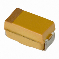
TAJA225K006RNJ
Description
CAP TANT 2.2UF 6.3V 10% SMD
Manufacturer
AVX Corporation
Series
TAJr
Type
Moldedr
Specifications of TAJA225K006RNJ
Capacitance
2.2µF
Package / Case
1206 (3216 Metric)
Voltage - Rated
6.3V
Tolerance
±10%
Operating Temperature
-55°C ~ 125°C
Mounting Type
Surface Mount
Size / Dimension
0.126" L x 0.063" W (3.20mm x 1.60mm)
Height
0.063" (1.60mm)
Manufacturer Size Code
A
Features
General Purpose
Tolerance (+ Or -)
10%
Voltage
6.3VDC
Esr
9Ohm
Mounting Style
Surface Mount
Polarity
Polar
Construction
SMT Chip
Case Style
Molded
Case Code
A
Lead Spacing (nom)
Not Requiredmm
Df
6%
Dcl
0.5uA
Seal
Not Required
Insulation
Not Required
Failure Rate
Not Required
Wire Form
Not Required
Product Length (mm)
3.2mm
Product Height (mm)
1.6mm
Product Depth (mm)
1.6mm
Product Diameter (mm)
Not Requiredmm
Seated Plane Height
Not Requiredmm
Length W/weld (max)
Not Requiredmm
Operating Temp Range
-55C to 125C
Lead Free Status / RoHS Status
Lead free / RoHS Compliant
Lead Spacing
-
Esr (equivalent Series Resistance)
-
Lead Free Status / RoHS Status
Compliant, Lead free / RoHS Compliant
Other names
TAJA225K006R
TAJA225K006R
TAJA225K006R


Technical Summary and
Application Guidelines
A piece of equipment was designed which would pass sine
and square wave currents of varying amplitudes through a
biased capacitor. The temperature rise seen on the body for
the capacitor was then measured using an infra-red probe.
This ensured that there was no heat loss through any ther-
mocouple attached to the capacitor’s surface.
Results for the C, D and E case sizes
Several capacitors were tested and the combined results are
shown above. All these capacitors were measured on FR4
board, with no other heatsinking. The ripple was supplied at
various frequencies from 1KHz to 1MHz.
As can be seen in the figure above, the average P
for the C case capacitors was 0.11 Watts. This is the same
as that quoted in Table I.
The D case capacitors gave an average P
Watts. This is lower than the value quoted in the Table I by
0.025 Watts.
The E case capacitors gave an average P
which was much higher than the 0.165 Watts from Table I.
If a typical capacitor’s ESR with frequency is considered, e.g.
figure below, it can be seen that there is variation. Thus for a
set ripple current, the amount of power to be dissipated by
the capacitor will vary with frequency. This is clearly shown in
figure in top of next column, which shows that the surface
temperature of the unit rises less for a given value of ripple
current at 1MHz than at 100KHz.
The graph below shows a typical ESR variation with fre-
quency. Typical ripple current versus temperature rise for
100KHz and 1MHz sine wave inputs.
42
0.01
0.1
1
100
100
90
80
70
60
50
40
30
20
10
0
0
0.1
1000
0.2
Power (Watts)
ESR vs. FREQUENCY
(TPSE107M016R0100)
0.3
Frequency (Hz)
10000
0.4
0.5
100000
max
max
of 0.200 Watts
value 0.125
C case
1000000
D case
E case
max
value
If I
fact coincident, as shown in figure below.
Example
A Tantalum capacitor is being used in a filtering application,
where it will be required to handle a 2 Amp peak-to-peak,
200KHz square wave current.
A square wave is the sum of an infinite series of sine waves
at all the odd harmonics of the square waves fundamental
frequency. The equation which relates is:
I
Thus the special components are:
Let us assume the capacitor is a TAJD686M006
Typical ESR measurements would yield.
Thus the total power dissipation would be 0.069 Watts.
From the D case results shown in figure top of previous
column, it can be seen that this power would cause the
capacitors surface temperature to rise by about 5°C.
For additional information, please refer to the AVX technical
publication “Ripple Rating of Tantalum Chip Capacitors” by
R.W. Franklin.
Square
2
R is then plotted it can be seen that the two lines are in
Frequency
Frequency
= I
70.00
60.00
50.00
40.00
30.00
20.00
10.00
200 KHz
600 KHz
200 KHz
600 KHz
1.4 MHz
1.4 MHz
0.00
1 MHz
1 MHz
70
60
40
20
pk
50
30
10
0
0.00
0.00
sin (2 ƒ) + I
0.05
0.20
0.10 0.15 0.20 0.25 0.30 0.35 0.40
pk
0.40
Peak-to-peak current
sin (6 ƒ) + I
RMS current (Amps)
Typical ESR
0.60
F
(Ohms)
(Amps)
R
2.000
0.667
0.400
0.286
0.120
0.115
0.090
0.100
pk
0.80
sin (10 ƒ) + I
1.00
0.45
1.20
0.50
Power (Watts)
pk
RMS current
Irms
sin (14 ƒ) +...
(Amps)
0.707
0.236
0.141
0.101
0.060
0.006
0.002
0.001
2
100KHz
1 MHz
100KHz
x ESR
1 MHz
Related parts for TAJA225K006RNJ
Image
Part Number
Description
Manufacturer
Datasheet
Request
R

Part Number:
Description:
Manufacturer:
AVX Corporation
Datasheet:
Part Number:
Description:
Manufacturer:
AVX Corporation
Datasheet:
Part Number:
Description:
Manufacturer:
AVX Corporation
Datasheet:
Part Number:
Description:
Manufacturer:
AVX Corporation
Datasheet:
Part Number:
Description:
Manufacturer:
AVX Corporation
Datasheet: