TAJA225K006RNJ AVX Corporation, TAJA225K006RNJ Datasheet - Page 18
TAJA225K006RNJ
Manufacturer Part Number
TAJA225K006RNJ
Description
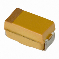
CAP TANT 2.2UF 6.3V 10% SMD
Manufacturer
AVX Corporation
Series
TAJr
Type
Moldedr
Specifications of TAJA225K006RNJ
Capacitance
2.2µF
Package / Case
1206 (3216 Metric)
Voltage - Rated
6.3V
Tolerance
±10%
Operating Temperature
-55°C ~ 125°C
Mounting Type
Surface Mount
Size / Dimension
0.126" L x 0.063" W (3.20mm x 1.60mm)
Height
0.063" (1.60mm)
Manufacturer Size Code
A
Features
General Purpose
Tolerance (+ Or -)
10%
Voltage
6.3VDC
Esr
9Ohm
Mounting Style
Surface Mount
Polarity
Polar
Construction
SMT Chip
Case Style
Molded
Case Code
A
Lead Spacing (nom)
Not Requiredmm
Df
6%
Dcl
0.5uA
Seal
Not Required
Insulation
Not Required
Failure Rate
Not Required
Wire Form
Not Required
Product Length (mm)
3.2mm
Product Height (mm)
1.6mm
Product Depth (mm)
1.6mm
Product Diameter (mm)
Not Requiredmm
Seated Plane Height
Not Requiredmm
Length W/weld (max)
Not Requiredmm
Operating Temp Range
-55C to 125C
Lead Free Status / RoHS Status
Lead free / RoHS Compliant
Lead Spacing
-
Esr (equivalent Series Resistance)
-
Lead Free Status / RoHS Status
Compliant, Lead free / RoHS Compliant
Other names
TAJA225K006R
TAJA225K006R
TAJA225K006R


Technical Summary and
Application Guidelines
So there is an order improvement in the capacitors steady-
state reliability.
Soldering Conditions and Board Attachment.
The soldering temperature and time should be the minimum
for a good connection.
A suitable combination for wavesoldering is 230 - 250°C for
3 - 5 seconds.
For vapor phase or infra-red reflow soldering the profile
below shows allowable and dangerous time/temperature
combinations. The profile refers to the peak reflow tempera-
Under the CECC 00 802 International
Specification, AVX Tantalum capacitors
are a Class A component.
46
Leakage current vs number of surge failures
Again, it must be remembered that these results were
derived from a highly accelerated surge test machine,
and failure rates in the low ppm are more likely with the end
customer.
AVX recommended derating table
SECTION 4
APPLICATION GUIDELINES FOR TANTALUM CAPACITORS
Standard leakage range
Classified Short Circuit
260
250
240
230
220
210
Over Catalog limit
50µA to 500µA
0.1 µA to 1µA
5µA to 50µA
0
ALLOWABLE
RANGE WITH CARE
Allowable range of peak temp./time combination for IR reflow
RECOMMENDED RANGE
Voltage Rail
3.3
10
12
15
5
24
15
TIME IN SECONDS
Number tested
10,000
10,000
10,000
30
Series Combinations (11)
Working Cap Voltage
DANGEROUS RANGE
Number failed surge
45
6.3
10
20
25
35
The capacitors can therefore be
subjected to one IR reflow, one wave
solder and one soldering iron cycle.
25
26
25
60
Temperature
( o C)
For further details on surge in Tantalum capacitors refer
to J.A. Gill’s paper “Surge in solid Tantalum capacitors”,
available from AVX offices worldwide.
An added bonus of increasing the derating applied in a
circuit, to improve the ability of the capacitor to withstand
surge conditions, is that the steady-state reliability is
improved by up to an order. Consider the example of a 6.3
volt capacitor being used on a 5 volt rail.
The steady-state reliability of a Tantalum capacitor is affected
by three parameters; temperature, series resistance and
voltage derating. Assume 40°C operation and 0.1
Ohms/Volt series resistance.
The capacitors reliability will therefore be:
If a 10 volt capacitor was used instead, the new scaling factor
would be 0.006, thus the steady-state reliability would be:
ture and is designed to ensure that the temperature of
the internal construction of the capacitor does not exceed
220°C. Preheat conditions vary according to the reflow
system used, maximum time and temperature would be 10
minutes at 150°C. Small parametric shifts may be noted
immediately after reflow, components should be allowed to
stabilize at room temperature prior to electrical testing.
Both TAJ and TAZ series are designed for reflow and wave
soldering operations. In addition TAZ is available with gold
terminations compatible with conductive epoxy or gold wire
bonding for hybrid assemblies.
Allowable range of peak temp./time combination for wave soldering
230
200
270
250
240
220
210
260
Failure rate = F
Failure rate = F
0
Allowable Range
with Preheat
2
Soldering Time (secs.)
= 0.15 x 0.1 x 1 x 1%/1000 hours
= 0.015%/1000 hours
= 0.006 x 0.1 x 1 x 1%/1000 hours
= 6 x 10
4
If more aggressive mounting tech-
niques are to be used please consult
AVX Tantalum for guidance.
U
U
x F
x F
Dangerous Range
6
T
T
-4
x F
x F
%/1000 hours
R
R
8
x 1%/1000 hours
x 1%/1000 hours
10
12
Allowable Range
with Care
Related parts for TAJA225K006RNJ
Image
Part Number
Description
Manufacturer
Datasheet
Request
R

Part Number:
Description:
Manufacturer:
AVX Corporation
Datasheet:
Part Number:
Description:
Manufacturer:
AVX Corporation
Datasheet:
Part Number:
Description:
Manufacturer:
AVX Corporation
Datasheet:
Part Number:
Description:
Manufacturer:
AVX Corporation
Datasheet:
Part Number:
Description:
Manufacturer:
AVX Corporation
Datasheet: