LD4T06P0 Red Lion Controls, LD4T06P0 Datasheet - Page 7
LD4T06P0
Manufacturer Part Number
LD4T06P0
Description
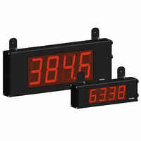
TIMER 6 DIGIT 4.0" 120VAC RED
Manufacturer
Red Lion Controls
Series
LDr
Type
Timerr
Specifications of LD4T06P0
No. Of Digits / Alpha
6
Digit Height
101mm
Power Consumption
26VA
Operating Temperature Range
0°C To +50°C
Signal Input Type
Pulse
Character Size
4"
Ip/nema Rating
IP65 / NEMA 4X
Signal Output Type
Relay
Accuracy
±0.01% %
Connection Type
Wire Leads
Dimensions
26"L×2.25"W×7.875"H
Display Digit Height
4 "
Display Resolution
0.001 Sec. (Minimum Digit), 1 hr. (Single Digit)
Display Type
LED
Function
Timer
Material, Casing
Aluminum
Number Of Digits
6
Primary Type
Electronic
Range, Measurement
0 to 999999
Special Features
RS485/RS232 Communications
Termination
Terminal Block
Voltage, Supply
85 to 250/11 to 16 VAC/VDC
Supply Voltage Range
21.6V DC To 250V DC
Count Speed Max
10Hz
External Depth
57.15mm
External Length / Height
200mm
Rohs Compliant
Yes
Counter Supply Voltage
85-250VAC/11-16VDC
Display Font Color
Red
Lead Free Status / RoHS Status
Lead free / RoHS Compliant
Lead Free Status / RoHS Status
Lead free / RoHS Compliant, Lead free / RoHS Compliant
Other names
RLC125


SECONDS
MINUTES
HOURS
status of the Timer. Timing diagrams are shown below for level active and edge
triggered (1-input or 2-input) operation. For single input modes (Input A only),
Input B provides a level active Timer Inhibit function. In the Display Hold
mode, the timer display value remains held and only updates when a Timer
Start (Input A) or Timer Stop (Input B) edge occurs.
diagrams, except the timer display value is reset at the Time Start edges.
activation or deactivation. This type of Stop condition is cleared when a Timer
Reset occurs, or another start edge is applied on the timer input.
SELECTION
5.1 MODULE 1 - T
Level Active (Gated) Operation
INPUT A
INPUT B - Timer Inhibit (Level Active)
PAR
RANGE
This parameter determines how the Timer Input Signals affect the Run/Stop
The timer reset (
The Timer can also be stopped at a Timer Stop Value or at Setpoint output
For Reset Modes (
Edge Triggered Operation - 2 Input
INPUT A
INPUT B
Range
Timer
,
,
Time
Start
Time
Start
MAXIMUM
DISPLAY
Time
Stop
Time
Stop
Timer Input
Operation
Time
Start
Time
Start
TIMER INPUT OPERATION
) operating modes are identical to the other modes in the
Time
Stop
RESOLUTION
), the timer is reset at Time Start edge.
DISPLAY
0.001 SEC
Time
Stop
18 TIMER RANGE SELECTIONS
(
0.01 SEC
TIMER RANGE
0.01 MIN
0.1 SEC
0.01 HR
0.1 MIN
0.1 HR
Timer Input
1 SEC
= SEC;
1 MIN
1 HR
Filter
= MIN;
MINUTES/SECONDS
HOURS/MINUTES
HOURS/MINUTES/SECONDS
DAYS/HOURS/MINUTES
SELECTION
Edge Triggered Operation - 2 Input,
with Display Hold
INPUT A
INPUT B
Edge Triggered Operation -1 Input
INPUT A
INPUT B - Timer Inhibit (Level Active)
RANGE
Direction
Timing
= HR;
Display Update
Time Start,
IMER
,
,
Time
Start
Display Update
Time Stop,
MAXIMUM
DISPLAY
= DAY
Display Update
Timer Start
Time Start,
Time
Stop
Value
PARAMETER MENU
)
Time
Start
I
RESOLUTION
NPUT
DISPLAY
Display
Update
0.01 SEC
0.01 MIN
0.1 SEC
0.1 MIN
Time
Stop
Timer Stop
1 SEC
1 SEC
1 MIN
1 MIN
Value
7
P
application.
entered in the same display format as the Timer Range selected. Non-zero
values are normally used for “timing down” applications, but they can also
provide an offset value when timing up.
the timer inputs. Selecting
entered in the same display format as the Timer Range selected. This stop
condition is cleared when a Timer Reset occurs or another start edge is applied
on the timer input. Select
does not apply to
ARAMETERS
Run Indicator
Flash Timer
Provides a 50 msec software debounce for the Timer Inputs (A and B). Select
Bi-directional timing capability. Select the timing direction desired for the
The Timer returns to this value whenever a Timer Reset occurs. The value is
The Timer stops when this value is reached regardless of the signal levels on
Select
Determines the Run/Stop state of the Timer at Power-up. This parameter
when using relays or switch contacts as a signal source.
- Timer Stopped at power-up, regardless of prior Run/Stop state
- Timer assumes the Run/Stop state it was in prior to power-down
to have the Timer Run indicator flash when the timer is running.
Timer Run
Power-up
State At
TIMER RUN STATE AT POWER-UP
FLASH TIMER RUN INDICATOR
TIMER START VALUE
TIMER INPUT FILTER
Input Operation.
TIMER STOP VALUE
TIMING DIRECTION
(
At Power-up
Timer Reset
if a Stop Value is not desired.
displays a sub-menu where the Stop Value is
to
to
User Input
)
Function
Assignment
User Input
Related parts for LD4T06P0
Image
Part Number
Description
Manufacturer
Datasheet
Request
R

Part Number:
Description:
Counter
Manufacturer:
Red Lion Controls
Datasheet:
Part Number:
Description:
Miniature Length Sensor
Manufacturer:
Red Lion Controls
Datasheet:
Part Number:
Description:
Model Lsc - Single Channel Output Length Sensor
Manufacturer:
Red Lion Controls
Datasheet: