LD4T06P0 Red Lion Controls, LD4T06P0 Datasheet - Page 6
LD4T06P0
Manufacturer Part Number
LD4T06P0
Description
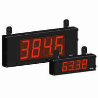
TIMER 6 DIGIT 4.0" 120VAC RED
Manufacturer
Red Lion Controls
Series
LDr
Type
Timerr
Specifications of LD4T06P0
No. Of Digits / Alpha
6
Digit Height
101mm
Power Consumption
26VA
Operating Temperature Range
0°C To +50°C
Signal Input Type
Pulse
Character Size
4"
Ip/nema Rating
IP65 / NEMA 4X
Signal Output Type
Relay
Accuracy
±0.01% %
Connection Type
Wire Leads
Dimensions
26"L×2.25"W×7.875"H
Display Digit Height
4 "
Display Resolution
0.001 Sec. (Minimum Digit), 1 hr. (Single Digit)
Display Type
LED
Function
Timer
Material, Casing
Aluminum
Number Of Digits
6
Primary Type
Electronic
Range, Measurement
0 to 999999
Special Features
RS485/RS232 Communications
Termination
Terminal Block
Voltage, Supply
85 to 250/11 to 16 VAC/VDC
Supply Voltage Range
21.6V DC To 250V DC
Count Speed Max
10Hz
External Depth
57.15mm
External Length / Height
200mm
Rohs Compliant
Yes
Counter Supply Voltage
85-250VAC/11-16VDC
Display Font Color
Red
Lead Free Status / RoHS Status
Lead free / RoHS Compliant
Lead Free Status / RoHS Status
Lead free / RoHS Compliant, Lead free / RoHS Compliant
Other names
RLC125


PROGRAMMING MODE ENTRY (PAR KEY)
installation. The meter normally operates in the Display Mode. No parameters
can be programmed in this mode. The Programming Mode is entered by
pressing the
code or a hardware lock (See Module 3).
MODULE ENTRY (SEL & PAR KEYS)
together parameters that are related in function. The display will alternate between
The displayed module is entered by pressing the
MODULE MENU (PAR KEY)
module discussion). The
to be changed, without changing the programming of preceding parameters.
After completing a module, the display will return to
may continue by accessing additional modules.
SELECTION / VALUE ENTRY
the selections/value for that parameter. The
move through the selections/values for that parameter. Pressing the
stores and activates the displayed selection/value. This also advances the meter
to the next parameter.
right most digit). Pressing the
can hold the
will select the next digit to the left. Pressing the
move to the next parameter.
OPERATING MODE DISPLAY DESIGNATORS
4.0 R
5.0 P
It is recommended all programming changes be made off line, or before
The Programming Menu is organized into five modules. These modules group
Each module has a separate module menu (which is shown at the start of each
For each parameter, the display alternates between the present parameter and
For numeric values, the value is displayed with one digit flashing (initially the
“
“
If display scroll is enabled, the display will toggle automatically every four seconds between the Timer and Cycle Counter values.
and the present module. The
” - To the left of the display is the Cycle Counter value.
”
- Between digits 5 and 6 indicates the setpoint status.
PAR
RST
key. If it is not accessible, then it is locked by either a security
RST
SEL
KEY
EVIEWING THE
PAR
ROGRAMMING THE
key and the digit will automatically scroll. The
PAR
DISPLAY
MODE
PAR
DISPLAY MODE OPERATION
Access Programming Mode
Select display (Timer or Cycle Counter)
Reset value(s) per front panel reset setting
key is pressed to advance to a particular parameter
RST
SEL
key increments the digit by one or the user
Timer Input
SEL
Parameters
key is used to select the desired module.
SEL and RST
PAR
PAR
PAR
key will enter the value and
key.
Cycle Counter
Parameters
PROGRAMMING MENU
F
keys are used to
. Programming
RONT
PAR
SEL
PAR
OVERVIEW
key,
key
M
Display and Front
6
ETER
P
Parameters
Panel Key
PROGRAMMING MODE EXIT (PAR KEY)
displayed. This will commit any stored parameter changes to memory and return
the meter to the Display Mode. (If power loss occurs before returning to the
Display Mode, verify recent parameter changes.)
PROGRAMMING TIPS
sequence. When programming is complete, it is recommended to record the
parameter programming and lock out parameter programming with the user input
or programming security code.
FACTORY SETTINGS
encountering programming problems.
ALTERNATING SELECTION DISPLAY
appear. This is used to illustrate the display alternating between the parameter
on top and the parameter’s Factory Setting on the bottom. In most cases,
selections and values for the parameter will be listed on the right.
“
The Programming Mode is exited by pressing the
It is recommended to start with Module 1 and proceed through each module in
Factory Settings may be completely restored in Module 3. This is useful when
In the explanation of the modules, the following dual display with arrows will
PROGRAMMING MODE OPERATION
Store selected parameter and index to next parameter
Advance through selection list/select digit position in
parameter value
Increment selected digit position of parameter value
ANEL
” - Decimal point to the far right of the display can be programmed to flash
PAR
when the timer is running, to provide a “Timer Run” indicator.
Parameter
Indicates Program Mode Alternating Display
K
Parameters
Setpoint
Output
EYS AND
Factory Settings are shown.
PAR
Parameters
Setup
Serial
Selection/Value
D
PAR
ISPLAY
PAR
key with
Related parts for LD4T06P0
Image
Part Number
Description
Manufacturer
Datasheet
Request
R

Part Number:
Description:
Counter
Manufacturer:
Red Lion Controls
Datasheet:
Part Number:
Description:
Miniature Length Sensor
Manufacturer:
Red Lion Controls
Datasheet:
Part Number:
Description:
Model Lsc - Single Channel Output Length Sensor
Manufacturer:
Red Lion Controls
Datasheet: