LD4T06P0 Red Lion Controls, LD4T06P0 Datasheet - Page 4
LD4T06P0
Manufacturer Part Number
LD4T06P0
Description
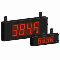
TIMER 6 DIGIT 4.0" 120VAC RED
Manufacturer
Red Lion Controls
Series
LDr
Type
Timerr
Specifications of LD4T06P0
No. Of Digits / Alpha
6
Digit Height
101mm
Power Consumption
26VA
Operating Temperature Range
0°C To +50°C
Signal Input Type
Pulse
Character Size
4"
Ip/nema Rating
IP65 / NEMA 4X
Signal Output Type
Relay
Accuracy
±0.01% %
Connection Type
Wire Leads
Dimensions
26"L×2.25"W×7.875"H
Display Digit Height
4 "
Display Resolution
0.001 Sec. (Minimum Digit), 1 hr. (Single Digit)
Display Type
LED
Function
Timer
Material, Casing
Aluminum
Number Of Digits
6
Primary Type
Electronic
Range, Measurement
0 to 999999
Special Features
RS485/RS232 Communications
Termination
Terminal Block
Voltage, Supply
85 to 250/11 to 16 VAC/VDC
Supply Voltage Range
21.6V DC To 250V DC
Count Speed Max
10Hz
External Depth
57.15mm
External Length / Height
200mm
Rohs Compliant
Yes
Counter Supply Voltage
85-250VAC/11-16VDC
Display Font Color
Red
Lead Free Status / RoHS Status
Lead free / RoHS Compliant
Lead Free Status / RoHS Status
Lead free / RoHS Compliant, Lead free / RoHS Compliant
Other names
RLC125


WIRING OVERVIEW
the meter. All conductors should conform to the meter's voltage and current
ratings. All cabling should conform to appropriate standards of good installation,
local codes and regulations. It is recommended that the power supplied to the
meter (DC or AC) be protected by a fuse or circuit breaker. When wiring the
meter, compare the numbers on the label on the back of the meter case against
those shown in wiring drawings for proper wire position. Strip the wire, leaving
approximately 0.4" (10 mm) bare lead exposed (stranded wires should be tinned
with solder.) Insert the lead under the correct screw clamp terminal and tighten
until the wire is secure. (Pull wire to verify tightness.) Each terminal can accept
up to one #14 AWG (2.55 mm) wire, two #18 AWG (1.02 mm), or four #20
AWG (0.61 mm). Use copper conductors only, with insulation rated at 90°C.
WIRING CONNECTIONS
Access to terminal blocks is through conduit fittings. Remove end plates with
¼" nut driver. For LD4 versions, all wiring is on right side of unit. For LD2
versions, power and input wiring connections are on the right side and the relay
and serial connections are on the left side.
inside the unit (right side). The DC out power is located on TBB (right side).
3.1 POWER WIRING
Power
Terminal 1: VAC/DC +
Terminal 2: VAC/DC -
Terminal 3: Protective Conductor
3.2 RESET/USER INPUT WIRING
Terminal 5: Reset/User Input
Terminal 6: User Common
3.3 SETPOINT (OUTPUT) WIRING
left side of the LD2 model, and on the right side for the LD4 model.
Terminal 1: Normally Closed
Terminal 2: Normally Open
Terminal 3: Relay Common
Electrical connections are made via pluggable terminal blocks located inside
Internal removable terminal blocks are used for power and signal wiring.
The power wiring is made via the 3 position terminal block (TBA) located
The Reset/User Input is located on the right side
The setpoint relay uses a three position terminal block (TBC) located on the
Terminal
+
-
2 NO
3
1 NC
COMMON
2
3
1
L1
L2
5
6
Sinking Logic
TBC
RESET/USER
COMM
TBA
DIP switch 6 OFF
4
DC Out Power
Terminal 4: + 24 VDC OUT
Terminal 6: User Common
Front
TBB
LD4
8
1
-
TBA
TBC
TBB
TBD
Sourcing Logic
4
6
5
6
DIP switch 6 ON
+ EXC
COMM
RESET/USER
COMM
TBC
TBD
Front
LD2 Right Side
LD2 Left Side
8
1
TBB
TBB
Front
TBA
TBB
Related parts for LD4T06P0
Image
Part Number
Description
Manufacturer
Datasheet
Request
R

Part Number:
Description:
Counter
Manufacturer:
Red Lion Controls
Datasheet:
Part Number:
Description:
Miniature Length Sensor
Manufacturer:
Red Lion Controls
Datasheet:
Part Number:
Description:
Model Lsc - Single Channel Output Length Sensor
Manufacturer:
Red Lion Controls
Datasheet: