EVAL-ADUM540XEBZ Analog Devices Inc, EVAL-ADUM540XEBZ Datasheet - Page 8
EVAL-ADUM540XEBZ
Manufacturer Part Number
EVAL-ADUM540XEBZ
Description
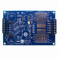
BOARD EVAL FOR ADUM540x
Manufacturer
Analog Devices Inc
Specifications of EVAL-ADUM540XEBZ
Main Purpose
Interface, Digital Isolator
Embedded
No
Utilized Ic / Part
ADuM540x, 520x, 500x, 130x, 131x, 140x, 141x, 240x, 330x, 340x
Primary Attributes
Pads for 16-SOP iCoupler® Isolators, Support for Signal Wrap Back
Secondary Attributes
Places for BNC Connectors for 50 Ohm Signals, Support for isoPower
Lead Free Status / RoHS Status
Lead free / RoHS Compliant


ADuM5401/ADuM5402/ADuM5403/ADuM5404
DIN V VDE V 0884-10 (VDE V 0884-10) INSULATION CHARACTERISTICS
These isolators are suitable for reinforced electrical isolation only within the safety limit data. Maintenance of the safety data is ensured by
protective circuits. The asterisk (*) marking on packages denotes DIN V VDE V 0884-10 approval.
Table 6.
Description
Installation Classification per DIN VDE 0110
Climatic Classification
Pollution Degree per DIN VDE 0110, Table 1
Maximum Working Insulation Voltage
Input-to-Output Test Voltage, Method b1
Input-to-Output Test Voltage, Method a
Highest Allowable Overvoltage
Safety Limiting Values
Insulation Resistance at T
RECOMMENDED OPERATING CONDITIONS
Table 7.
Parameter
Operating Temperature
Supply Voltages
Minimum Load
1
2
3
Operation at 105°C requires reduction of the maximum load current, as specified in
All voltages are relative to their respective ground.
If the external load is less than the specified value, the power supply PWM can generate excess switching noise, potentially causing data integrity issues.
V
V
For Rated Mains Voltage ≤ 150 V rms
For Rated Mains Voltage ≤ 300 V rms
For Rated Mains Voltage ≤ 400 V rms
After Environmental Tests Subgroup 1
After Input and/or Safety Test Subgroup 2
Case Temperature
Side 1 I
DD1
DD1
and Subgroup 3
@ V
@ V
DD1
SEL
SEL
Current
= 0 V
= V
3
2
ISO
Figure 6. Thermal Derating Curve, Dependence of Safety Limiting Values on Case Temperature, per DIN EN 60747-5-2
1
S
600
500
400
300
200
100
0
0
Conditions
V
partial discharge < 5 pC
V
V
Transient overvoltage, t
Maximum value allowed in the event of a failure
(see Figure 6)
V
IORM
IORM
IORM
IO
= 500 V
× 1.875 = V
× 1.6 = V
× 1.2 = V
50
AMBIENT TEMPERATURE (°C)
Rev. A | Page 8 of 24
PR
PR
Symbol
T
V
V
I
, t
, t
ISO(MIN)
A
PR
DD1
DD1
m
m
, 100% production test, t
= 60 sec, partial discharge < 5 pC
= 60 sec, partial discharge < 5 pC
100
Table 8
TR
= 10 sec
.
150
Min
−40
3.0
4.5
10
m
= 1 sec,
200
Symbol
V
V
V
V
T
I
R
S1
S
IORM
PR
PR
TR
S
Max
+85
3.6
5.5
Characteristic
I to IV
I to III
I to II
40/105/21
2
560
1050
896
672
4000
150
555
>10
9
Unit
°C
V
V
mA
Unit
V peak
V peak
V peak
V peak
V peak
°C
mA
Ω
Related parts for EVAL-ADUM540XEBZ
Image
Part Number
Description
Manufacturer
Datasheet
Request
R

Part Number:
Description:
EVAL BD For QSOP & SOIC16 Dig Isolators
Manufacturer:
Analog Devices Inc
Datasheet:

Part Number:
Description:
IC, ADJ LDO REG, 1.5V TO 5V 250mA MSOP-8
Manufacturer:
Vishay
Datasheet:

Part Number:
Description:
IC, ADJ LDO REG, 1.5V TO 5V 0.6A 8-TSSOP
Manufacturer:
Vishay
Datasheet:
Part Number:
Description:
IC, ADJ LDO REG, 1.5V TO 5V 250mA MSOP-8
Manufacturer:
Vishay
Datasheet:

Part Number:
Description:
IC ADJ LDO REG 1.5V TO 5V 150mA 5-SOT-23
Manufacturer:
Vishay
Datasheet:

Part Number:
Description:
BOARD EVAL AS1324-AD
Manufacturer:
austriamicrosystems
Datasheet:
Part Number:
Description:
IC, ADJ LDO REG, 1.5V TO 5V 0.6A 8-TSSOP
Manufacturer:
Vishay
Datasheet:

Part Number:
Description:
IC, ADJ LDO REG, 1.5V TO 5V, 0.3A, MSOP8
Manufacturer:
Vishay
Datasheet:
Part Number:
Description:
IC, ADJ LDO REG, 1.5V TO 5V, 0.3A, MSOP8
Manufacturer:
Vishay
Datasheet:
Part Number:
Description:
IC, ADJ LDO REG 1.215V TO 5V 0.3A MSOP-8
Manufacturer:
Vishay
Datasheet:

Part Number:
Description:
±1.7g Dual-Axis IMEMS Accelerometer Evaluation Board
Manufacturer:
Analog Devices Inc
Datasheet:

Part Number:
Description:
IC MULTIPLIER ANALOG 8-SOIC T/R
Manufacturer:
Analog Devices Inc
Datasheet:
Part Number:
Description:
IC ANALOG MULTIPLIER 8-DIP
Manufacturer:
Analog Devices Inc
Datasheet:
Part Number:
Description:
IC ANALOG MULTIPLIER 8-SOIC
Manufacturer:
Analog Devices Inc
Datasheet:
Part Number:
Description:
IC ANALOG MULTIPLIER 8-DIP
Manufacturer:
Analog Devices Inc
Datasheet: