EVAL-ADUM540XEBZ Analog Devices Inc, EVAL-ADUM540XEBZ Datasheet - Page 19
EVAL-ADUM540XEBZ
Manufacturer Part Number
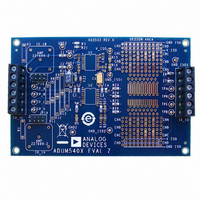
EVAL-ADUM540XEBZ
Description
BOARD EVAL FOR ADUM540x
Manufacturer
Analog Devices Inc
Specifications of EVAL-ADUM540XEBZ
Main Purpose
Interface, Digital Isolator
Embedded
No
Utilized Ic / Part
ADuM540x, 520x, 500x, 130x, 131x, 140x, 141x, 240x, 330x, 340x
Primary Attributes
Pads for 16-SOP iCoupler® Isolators, Support for Signal Wrap Back
Secondary Attributes
Places for BNC Connectors for 50 Ohm Signals, Support for isoPower
Lead Free Status / RoHS Status
Lead free / RoHS Compliant


For example, at a magnetic field frequency of 1 MHz, the
maximum allowable magnetic field of 0.2 kGauss induces a
voltage of 0.25 V at the receiving coil. This is about 50% of the
sensing threshold and does not cause a faulty output transition.
Similarly, if such an event occurs during a transmitted pulse
(and is of the worst-case polarity), it reduces the received pulse
from >1.0 V to 0.75 V, which is still well above the 0.5 V sensing
threshold of the decoder.
The preceding magnetic flux density values correspond to specific
current magnitudes at given distances from the ADuM5401/
ADuM5402/ADuM5403/ADuM5404 transformers. Figure 26
expresses these allowable current magnitudes as a function
of frequency for selected distances. As shown in Figure 26, the
ADuM5401/ADuM5402/ADuM5403/ADuM5404 are immune
and can be affected only by large currents operated at high
frequency very close to the component. For the 1 MHz example,
a 0.5 kA current would need to be placed 5 mm away from the
ADuM5401/ADuM5402/ADuM5403/ADuM5404 to affect
component operation.
In combinations of strong magnetic field and high frequency,
any loops formed by PCB traces cand induce error voltages
sufficiently large to trigger the thresholds of succeeding circuitry.
To avoid this, care should be taken in the layout of such traces.
POWER CONSUMPTION
The V
data channels, as well as to the power converter. For this reason,
the quiescent currents drawn by the data converter and the
primary and secondary I/O channels cannot be determined
separately. All of these quiescent power demands have been
combined into the I
total I
operating current; the dynamic current, I
the I/O channels; and any external I
0.01
100
Figure 26. Maximum Allowable Current for Various Current-to-
DD1
DD1
0.1
1k
10
1
ADuM5401/ADuM5402/ADuM5403/ADuM5404 Spacings
1k
supply current is equal to the sum of the quiescent
power supply input provides power to the iCoupler
DISTANCE = 100mm
10k
DISTANCE = 5mm
DD1(Q)
MAGNETIC FIELD FREQUENCY (Hz)
current, as shown in Figure 27. The
100k
ISO
1M
load.
DISTANCE = 1m
DD1(D)
10M
, demanded by
100M
Rev. A | Page 19 of 24
ADuM5401/ADuM5402/ADuM5403/ADuM5404
Dynamic I/O current is consumed only when operating a channel
at speeds higher than the refresh rate of f
of each channel is determined by its data rate. Figure 19 shows the
current for a channel in the forward direction, meaning that the
input is on the V
for a channel in the reverse direction, meaning that the input is on
the V
15 pF load.
The following relationship allows the total I
calculated:
where:
I
I
E is the power supply efficiency at 100 mA load from Figure 11
at the V
I
Figure 19 or Figure 20, depending on channel direction.
The maximum external load can be calculated by subtracting
the dynamic output load from the maximum allowable load.
where:
I
side load.
I
available at V
I
or output channel, as shown in Figure 21 and Figure 22.
The preceding analysis assumes a 15 pF capacitive load on each
data output. If the capacitive load is larger than 15 pF, the additional
current must be included in the analysis of I
DD1
ISO
CHn
ISO(LOAD)
ISO(MAX)
ISO(D)n
is the current drawn by the secondary side external load.
is the total supply input current.
is the current drawn by a single channel determined from
I
I
ISO
DD1
ISO(LOAD)
I
I
is the dynamic load current drawn from V
DD1(Q)
DD1(D)
is the maximum external secondary side load current
ISO
side of the part. Figure 19 and Figure 20 assume a typical
is the current available to supply an external secondary
= (I
and V
ADuM5401/ADuM5402/ADuM5403/ADuM5404
ISO
= I
ISO
Figure 27. Power Consumption Within the
× V
.
CONVERTER
ISO(MAX)
DD1
DD1
PRIMARY
PRIMARY
I
DATA
DDP(D)
ISO
4CH
I/O
side of the part. Figure 20 shows the current
condition of interest.
)/(E × V
− Σ I
ISO(D)n
DD1
E
) + Σ I
; n = 1 to 4
CONVERTER
SECONDARY
SECONDARY
CHn
DATA
4CH
I/O
I
ISO(D)
r
; n = 1 to 4
. The dynamic current
DD1
DD1
current to be
and I
ISO
by an input
I
ISO(LOAD)
ISO
.
(2)
(1)
Related parts for EVAL-ADUM540XEBZ
Image
Part Number
Description
Manufacturer
Datasheet
Request
R

Part Number:
Description:
EVAL BD For QSOP & SOIC16 Dig Isolators
Manufacturer:
Analog Devices Inc
Datasheet:

Part Number:
Description:
IC, ADJ LDO REG, 1.5V TO 5V 250mA MSOP-8
Manufacturer:
Vishay
Datasheet:

Part Number:
Description:
IC, ADJ LDO REG, 1.5V TO 5V 0.6A 8-TSSOP
Manufacturer:
Vishay
Datasheet:
Part Number:
Description:
IC, ADJ LDO REG, 1.5V TO 5V 250mA MSOP-8
Manufacturer:
Vishay
Datasheet:

Part Number:
Description:
IC ADJ LDO REG 1.5V TO 5V 150mA 5-SOT-23
Manufacturer:
Vishay
Datasheet:

Part Number:
Description:
BOARD EVAL AS1324-AD
Manufacturer:
austriamicrosystems
Datasheet:
Part Number:
Description:
IC, ADJ LDO REG, 1.5V TO 5V 0.6A 8-TSSOP
Manufacturer:
Vishay
Datasheet:

Part Number:
Description:
IC, ADJ LDO REG, 1.5V TO 5V, 0.3A, MSOP8
Manufacturer:
Vishay
Datasheet:
Part Number:
Description:
IC, ADJ LDO REG, 1.5V TO 5V, 0.3A, MSOP8
Manufacturer:
Vishay
Datasheet:
Part Number:
Description:
IC, ADJ LDO REG 1.215V TO 5V 0.3A MSOP-8
Manufacturer:
Vishay
Datasheet:

Part Number:
Description:
±1.7g Dual-Axis IMEMS Accelerometer Evaluation Board
Manufacturer:
Analog Devices Inc
Datasheet:

Part Number:
Description:
IC MULTIPLIER ANALOG 8-SOIC T/R
Manufacturer:
Analog Devices Inc
Datasheet:
Part Number:
Description:
IC ANALOG MULTIPLIER 8-DIP
Manufacturer:
Analog Devices Inc
Datasheet:
Part Number:
Description:
IC ANALOG MULTIPLIER 8-SOIC
Manufacturer:
Analog Devices Inc
Datasheet:
Part Number:
Description:
IC ANALOG MULTIPLIER 8-DIP
Manufacturer:
Analog Devices Inc
Datasheet: