EVAL-ADUM540XEBZ Analog Devices Inc, EVAL-ADUM540XEBZ Datasheet - Page 7
EVAL-ADUM540XEBZ
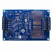
Manufacturer Part Number
EVAL-ADUM540XEBZ
Description
BOARD EVAL FOR ADUM540x
Manufacturer
Analog Devices Inc
Specifications of EVAL-ADUM540XEBZ
Main Purpose
Interface, Digital Isolator
Embedded
No
Utilized Ic / Part
ADuM540x, 520x, 500x, 130x, 131x, 140x, 141x, 240x, 330x, 340x
Primary Attributes
Pads for 16-SOP iCoupler® Isolators, Support for Signal Wrap Back
Secondary Attributes
Places for BNC Connectors for 50 Ohm Signals, Support for isoPower
Lead Free Status / RoHS Status
Lead free / RoHS Compliant


PACKAGE CHARACTERISTICS
Table 3.
Parameter
Resistance (Input to Output)
Capacitance (Input to Output)
Input Capacitance
IC Junction-to-Ambient Thermal Resistance
1
2
3
REGULATORY APPROVALS
Table 4.
UL
Recognized under the UL1577
Single protection, 2500 V rms
File E214100
1
2
INSULATION AND SAFETY-RELATED SPECIFICATIONS
Table 5.
Parameter
Rated Dielectric Insulation Voltage
Minimum External Air Gap (Clearance)
Minimum External Tracking (Creepage)
Minimum Internal Gap (Internal Clearance)
Tracking Resistance (Comparative Tracking Index) CTI
Isolation Group
The device is considered a 2-terminal device: Pin 1 to Pin 8 are shorted together, and Pin 9 to Pin 16 are shorted together.
Input capacitance is from any input data pin to ground.
See the
In accordance with UL1577, each ADuM5401/ADuM5402/ADuM5403/ADuM5404 is proof tested by applying an insulation test voltage of ≥3000 V rms for 1 sec
(current leakage detection limit = 10 μA).
In accordance with DIN V VDE V 0884-10, each of the ADuM5401/ADuM5402/ADuM5403/ADuM5404 is proof tested by applying an insulation test voltage of
≥1050 V peak for 1 sec (partial discharge detection limit = 5 pC). The asterisk (*) marking branded on the component designates DIN V VDE V 0884-10 approval.
component recognition
program
isolation voltage
Thermal Analysis
1
2
section for thermal model definitions.
1
1
CSA (Pending)
Approved under CSA Component Acceptance Notice #5A
Reinforced insulation per CSA 60950-1-03 and IEC 60950-1,
400 V rms (566 V peak) maximum working voltage
File 205078
Symbol
R
C
C
θ
I-O
JA
I-O
I
Symbol
L(I01)
L(I02)
Min
Rev. A | Page 7 of 24
Typ
10
2.2
4.0
45
Value
2500
>8.0
>8.0
0.017
>175
IIIa
12
ADuM5401/ADuM5402/ADuM5403/ADuM5404
Max
Unit
V rms
mm
mm
mm min
V
Unit
Ω
pF
pF
°C/W
Test Conditions
f = 1 MHz
Thermocouple located at center of package underside,
test conducted on 4-layer board with thin traces
Test Conditions/Comments
1-minute duration
Measured from input terminals to output terminals,
shortest distance through air
Measured from input terminals to output terminals,
shortest distance path along body
Distance through insulation
DIN IEC 112/VDE 0303, Part 1
Material Group (DIN VDE 0110, 1/89, Table 1)
VDE (Pending)
Certified according to DIN V VDE V 0884-10
(VDE V 0884-10):2006-12
Reinforced insulation, 560 V peak
File 2471900-4880-0001
2
3
Related parts for EVAL-ADUM540XEBZ
Image
Part Number
Description
Manufacturer
Datasheet
Request
R

Part Number:
Description:
EVAL BD For QSOP & SOIC16 Dig Isolators
Manufacturer:
Analog Devices Inc
Datasheet:

Part Number:
Description:
IC, ADJ LDO REG, 1.5V TO 5V 250mA MSOP-8
Manufacturer:
Vishay
Datasheet:

Part Number:
Description:
IC, ADJ LDO REG, 1.5V TO 5V 0.6A 8-TSSOP
Manufacturer:
Vishay
Datasheet:
Part Number:
Description:
IC, ADJ LDO REG, 1.5V TO 5V 250mA MSOP-8
Manufacturer:
Vishay
Datasheet:

Part Number:
Description:
IC ADJ LDO REG 1.5V TO 5V 150mA 5-SOT-23
Manufacturer:
Vishay
Datasheet:

Part Number:
Description:
BOARD EVAL AS1324-AD
Manufacturer:
austriamicrosystems
Datasheet:
Part Number:
Description:
IC, ADJ LDO REG, 1.5V TO 5V 0.6A 8-TSSOP
Manufacturer:
Vishay
Datasheet:

Part Number:
Description:
IC, ADJ LDO REG, 1.5V TO 5V, 0.3A, MSOP8
Manufacturer:
Vishay
Datasheet:
Part Number:
Description:
IC, ADJ LDO REG, 1.5V TO 5V, 0.3A, MSOP8
Manufacturer:
Vishay
Datasheet:
Part Number:
Description:
IC, ADJ LDO REG 1.215V TO 5V 0.3A MSOP-8
Manufacturer:
Vishay
Datasheet:

Part Number:
Description:
±1.7g Dual-Axis IMEMS Accelerometer Evaluation Board
Manufacturer:
Analog Devices Inc
Datasheet:

Part Number:
Description:
IC MULTIPLIER ANALOG 8-SOIC T/R
Manufacturer:
Analog Devices Inc
Datasheet:
Part Number:
Description:
IC ANALOG MULTIPLIER 8-DIP
Manufacturer:
Analog Devices Inc
Datasheet:
Part Number:
Description:
IC ANALOG MULTIPLIER 8-SOIC
Manufacturer:
Analog Devices Inc
Datasheet:
Part Number:
Description:
IC ANALOG MULTIPLIER 8-DIP
Manufacturer:
Analog Devices Inc
Datasheet: