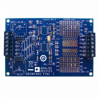
EVAL-ADUM540XEBZ Analog Devices Inc, EVAL-ADUM540XEBZ Datasheet - Page 13

EVAL-ADUM540XEBZ
Manufacturer Part Number
EVAL-ADUM540XEBZ
Description
BOARD EVAL FOR ADUM540x
Manufacturer
Analog Devices Inc
Specifications of EVAL-ADUM540XEBZ
Main Purpose
Interface, Digital Isolator
Embedded
No
Utilized Ic / Part
ADuM540x, 520x, 500x, 130x, 131x, 140x, 141x, 240x, 330x, 340x
Primary Attributes
Pads for 16-SOP iCoupler® Isolators, Support for Signal Wrap Back
Secondary Attributes
Places for BNC Connectors for 50 Ohm Signals, Support for isoPower
Lead Free Status / RoHS Status
Lead free / RoHS Compliant
Table 13. ADuM5404 Pin Function Descriptions
Pin No. Mnemonic Description
1
2, 8
3
4
5
6
7
9, 15
10
11
12
13
14
16
TRUTH TABLE
Table 14. Truth Table (Positive Logic)
V
High
Low
High
Low
High
Low
High
Low
1
V
Ix
Ix
and V
Input
Ox
V
GND
V
V
V
V
RC
GND
V
V
V
V
V
V
1
refer to the input and output signals of a given channel (A, B, C, or D).
DD1
OA
OB
OC
OD
SEL
ID
IC
IB
IA
ISO
OUT
V
High
High
Low
Low
Low
Low
High
High
1
ISO
SEL
Input
Primary Supply Voltage, 3.0 V to 5.5 V.
Ground 1. Ground reference for isolator primary. Pin 2 and Pin 8 are internally connected to each other. It is
recommended that both pins be connected to a common ground.
Logic Output A.
Logic Output B.
Logic Output C.
Logic Output D.
Regulation Control Output. This pin is connected to the RC
to control the regulation of the slave device.
Ground Reference for Isolator Side 2. Pin 9 and Pin 15 are internally connected to each other. It is recommended that
both pins be connected to a common ground.
Output Voltage Selection. When V
Logic Input D.
Logic Input C.
Logic Input B.
Logic Input A.
Secondary Supply Voltage Output for Data Channels and External Loads.
V
Powered
Powered
Powered
Powered
Powered
Powered
Powered
Powered
DD1
State
V
5.0
5.0
3.3
3.3
5.0
5.0
3.3
3.3
DD1
Input (V)
Figure 10. ADuM5404 Pin Configuration
RC
GND
GND
V
SEL
V
V
V
V
OUT
DD1
OB
OC
OD
OA
V
Powered
Powered
Powered
Powered
Powered
Powered
Powered
Powered
1
1
= V
ISO
1
2
3
4
5
6
7
8
Rev. A | Page 13 of 24
ISO
State
ADuM5404
(Not to Scale)
, the V
TOP VIEW
ADuM5401/ADuM5402/ADuM5403/ADuM5404
ISO
V
5.0
5.0
3.3
3.3
3.3
3.3
5.0
5.0
setpoint is 5.0 V. When V
ISO
16
15
14
13
12
11
10
Output (V)
9
V
GND
V
V
V
V
V
GND
ISO
IA
IB
IC
ID
SEL
IN
ISO
ISO
of a slave isoPower device to allow the ADuM5404
V
High
Low
High
Low
High
Low
High
Low
Ox
Output
SEL
= GND
1
Notes
Normal operation, data is high
Normal operation, data is low
Normal operation, data is high
Normal operation, data is low
Configuration not recommended
Configuration not recommended
Configuration not recommended
Configuration not recommended
ISO
, the V
ISO
setpoint is 3.3 V.


