AD9777-EB Analog Devices Inc, AD9777-EB Datasheet - Page 35
AD9777-EB
Manufacturer Part Number
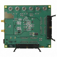
AD9777-EB
Description
BOARD EVAL FOR AD9777
Manufacturer
Analog Devices Inc
Series
TxDAC+®r
Datasheet
1.AD9777BSVZ.pdf
(60 pages)
Specifications of AD9777-EB
Rohs Status
RoHS non-compliant
Number Of Dac's
2
Number Of Bits
16
Outputs And Type
2, Differential
Sampling Rate (per Second)
160M
Data Interface
Parallel
Settling Time
11ns
Dac Type
Current
Voltage Supply Source
Analog and Digital
Operating Temperature
-40°C ~ 85°C
Utilized Ic / Part
AD9777


MODULATION, INTERPOLATION = 2×
With Control Register 01h, Bit 7 and Bit 6 set to 01, the
interpolation rate of the AD9777 is 2×. Modulation is achieved
by multiplying successive samples at the interpolation filter
output by the sequence (+1, −1). Figure 63 to Figure 66
represent the spectral response of the AD9777 DAC output with
2× interpolation in the various modulation modes to a narrow
band baseband signal (again, the tall rectangles in the graphic).
The advantage of interpolation becomes clear in Figure 63 to
Figure 66, where it can be seen that the images that would
normally appear in the spectrum around the significant point is
that the interpolation filtering is done prior to the digital
modulator.
The Effects of Digital Modulation on DAC Output Spectrum, Interpolation = 2x
–100
–100
–20
–40
–60
–80
–20
–40
–60
–80
0
0
0
0
Figure 63. 2× Interpolation, Modulation = Disabled
Figure 64. 2× Interpolation, Modulation = f
0.5
0.5
f
f
OUT
OUT
1.0
1.0
( ×
( ×
f
f
DATA
DATA
)
)
1.5
1.5
DAC
/2
2.0
2.0
Rev. C | Page 35 of 60
For this reason, as Figure 63 to Figure 66 show, the pass band of
the interpolation filters can be frequency shifted, giving the
equivalent of a high-pass digital filter.
Note that when using the f
true stop band as the band edges coincide with each other. In
the f
portion of the digital filter pass band due to constructive
addition over just that section of the band
–100
–100
–20
–40
–60
–80
S
–20
–40
–60
–80
/8 modulation mode, amplitude scaling occurs over only a
0
0
0
0
Figure 65. 2× Interpolation, Modulation = f
Figure 66. 2× Interpolation, Modulation = f
0.5
0.5
S
f
f
/4 modulation mode, there is no
OUT
OUT
1.0
1.0
( ×
( ×
f
f
DATA
DATA
)
)
1.5
1.5
DAC
DAC
/4
/8
AD9777
2.0
2.0
Related parts for AD9777-EB
Image
Part Number
Description
Manufacturer
Datasheet
Request
R

Part Number:
Description:
16Bit 400 MSPS Dual TxDAC+ D/A Converter
Manufacturer:
Analog Devices Inc
Datasheet:

Part Number:
Description:
±1.7g Dual-Axis IMEMS Accelerometer Evaluation Board
Manufacturer:
Analog Devices Inc
Datasheet:
Part Number:
Description:
Inertial Sensor Evaluation System
Manufacturer:
Analog Devices Inc
Datasheet:
Part Number:
Description:
Manufacturer:
Analog Devices Inc
Datasheet:
Part Number:
Description:
Manufacturer:
Analog Devices Inc
Datasheet:
Part Number:
Description:
Manufacturer:
Analog Devices Inc
Datasheet:
Part Number:
Description:
Manufacturer:
Analog Devices Inc
Datasheet:
Part Number:
Description:
Manufacturer:
Analog Devices Inc
Datasheet:
Part Number:
Description:
Manufacturer:
Analog Devices Inc
Datasheet:
Part Number:
Description:
Manufacturer:
Analog Devices Inc
Datasheet:
Part Number:
Description:
Manufacturer:
Analog Devices Inc
Datasheet:
Part Number:
Description:
Manufacturer:
Analog Devices Inc
Datasheet:
Part Number:
Description:
Manufacturer:
Analog Devices Inc
Datasheet: