ADZS-HPUSB-ICE Analog Devices Inc, ADZS-HPUSB-ICE Datasheet
ADZS-HPUSB-ICE
Specifications of ADZS-HPUSB-ICE
ADZU-HPUSB-ICE
Available stocks


Related parts for ADZS-HPUSB-ICE


ADZS-HPUSB-ICE Summary of contents
Page 1
Analog Devices, Inc. One Technology Way Norwood, Mass. 02062-9106 HPUSB, USB, HPPCI and MSP430 Emulators Users Guide Revision 3.0, December 2007 Part Number 82-000760-01 a ...
Page 2
Copyright Information ©2007 Analog Devices, Inc., ALL RIGHTS RESERVED. This document may not be reproduced in any form without prior, express written consent from Analog Devices, Inc. Printed in the USA. Notice Analog Devices, Inc. reserves the right to make ...
Page 3
Limited Warranty The USB- and PCI-based emulators hardware is warranted against defects in materials and workmanship for a period of one year from the date of purchase from Analog Devices or from an authorized dealer. Trademark and Service Mark Notice ...
Page 4
The USB- and PCI-based emulators have been appended to Analog Devices Development Tools Technical Construction File referenced “DSPTOOLS1” dated December 21, 1997 and was awarded CE Certifi- cation by an appointed European Competent Body and is on file. The EZ-KIT ...
Page 5
CONTENTS PREFACE Purpose of This Manual .................................................................. ix Intended Audience .......................................................................... ix Manual Contents ............................................................................. x Technical or Customer Support ........................................................ x GETTING STARTED Contents of Emulator Package ....................................................... 1-2 PC Configuration ......................................................................... 1-2 Installation Tasks .......................................................................... 1-3 Installing USB-Based ...
Page 6
CONTENTS HPUSB/USB Legacy Mode ................................................... 1-13 HPPCI-ICE Legacy/Auto Detection Mode ............................ 1-13 Legacy Mode (Factory Default Setting) .................................. 1-14 Auto Detection Mode ........................................................... 1-15 Troubleshooting Emulator Problems ........................................... 1-17 HARDWARE DESCRIPTION LEDs ........................................................................................... 2-1 HPUSB-ICE/USB-ICE LEDs ................................................. 2-1 HPPCI-ICE LEDs ...
Page 7
PREFACE Thank you for purchasing an Analog Devices USB- or PCI-based JTAG emulator. The USB-based emulator family consists of the High-Perfor- mance USB JTAG emulator, the USB JTAG emulator, and the MS430 emulator. The USB- and PCI-based emulators are used ...
Page 8
The HPPCI-ICE system provides state-of-the-art support for JTAG-compliant Analog Devices processors. Key features of the HPPCI-ICE include: • Plug-n-Play, PCI 2.2 compliant • Windows 2000, Windows XP, or Windows Vista operation • Multiple processor I/O voltage support 1.8V, 2.5V, and ...
Page 9
The MSP430-ICE system provides state-of-the-art support for selected processors within the Analog Devices MSP430 processor family. Key features of the MSP430-ICE include: • Plug-n-Play, USB 2.0 compliant • Full-speed USB device • Windows 2000, Windows XP, or Windows Vista operation ...
Page 10
Manual Contents Manual Contents The manual consists of: • Chapter 1, “Getting Started” on page 1-1 Provides software and hardware installation procedures, PC system requirements, and basic board information. • Chapter 2, “Hardware Description” on page 2-1 Provides information on ...
Page 11
Contact your Analog Devices, Inc. local sales office or authorized distributor • Send questions by mail to: Analog Devices, Inc. One Technology Way P.O. Box 9106 Norwood, MA 02062-9106 USA HPUSB, USB, HPPCI and MSP430 Emulators User’s Guide Preface ...
Page 12
Technical or Customer Support xii HPUSB, USB, HPPCI and MSP430 Emulators User’s Guide ...
Page 13
GETTING STARTED This chapter provides the information needed to begin using Analog Devices USB- and PCI-based emulators. This chapter includes the following sections. • “Contents of Emulator Package” on page 1-2 Provides a list of the components that are ...
Page 14
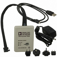
Contents of Emulator Package Contents of Emulator Package USB-Based Emulator: Your USB-based emulator package contains the following items. • HPUSB-ICE, USB-ICE, or MSP430 assembly • 5-volt power supply • 3-meter USB type-A to mini-B cable HPPCI-ICE Emulator: Your High-Performance PCI ...
Page 15
Installation Tasks Perform the following tasks to safely install your USB- or PCI-based emulator. Follow these instructions in the presented order to ensure correct operation of your software and hardware. Installing USB-Based Emulators 1. Install VisualDSP++ 3.5 or later. VisualDSP++ ...
Page 16
Installation Tasks Installing PCI-Based Emulators 1. Install the HPPCI-ICE hardware. For instructions on installing a PCI card into your computer, consult the documentation provided by the computer manufacturer. 2. Install VisualDSP++ 3.5 or later. VisualDSP++ includes the HPPCI driver needed ...
Page 17
Figure 1-1. Verifying Driver Installation HPUSB, USB, HPPCI and MSP430 Emulators User’s Guide Getting Started 1-5 ...
Page 18
Attaching the Cable to the Emulation Target Attaching the Cable to the Emulation Target HPUSB, HPPCI, USB JTAG ICEs (not MSP430) The final step is to connect the 14-pin header side of the pod cable to the target board via ...
Page 19
Power down the ICE. 4. Power down the target board. If the emulator has an “Enable/Power” LED, this should be green when power is applied. It should be amber when connected to a session or the ICE Test utility ...
Page 20
VisualDSP++ Configurator 3. Connect the USB cable between the ICE and the PC. 4. Invoke VisualDSP++. To power down the MSP430 emulator: 1. Shut down (exit) VisualDSP++. 2. Disconnect the USB cable between the ICE and the PC. 3. Power ...
Page 21
The VisualDSP++ Configurator’s ICE Test utility allows you to configure and test your emulator hardware. ICE Test provides emulator detection, JTAG I/O voltage selection, and JTAG frequency selection. Use the ICE Test to test the target. If errors are encountered, ...
Page 22
JTAG Frequency Selection Figure 1-2. HPUSB-ICE JTAG Frequency Selection Dialog Box Figure 1-3. HPPCI-ICE JTAG Frequency Selection Dialog Box 1-10 HPUSB, USB, HPPCI and MSP430 Emulators User’s Guide ...
Page 23
Cancel button goes back to using the frequency pointed to by the blue arrow. To use a different frequency, select the appropriate frequency from the list and click Test. Clicking OK uses the frequency ...
Page 24
HPPCI JTAG I/O Voltage Detection HPPCI JTAG I/O Voltage Detection The mode of operation supported by the PCI emulator is dependent on the connection method used for the 14-pin JTAG header on your target. Figure 1-4 and Figure 1-5 legacy ...
Page 25
GND 1 Key (no pin) Target VDDIO / BTMS 5 BTCK 7 BTRST 9 BTDI 11 GND 13 Figure 1-5. Auto Detection Pinout HPUSB/USB Legacy Mode Legacy mode is used for older targets that do not provide a target VDDIO ...
Page 26
HPPCI JTAG I/O Voltage Detection In order to modify the factory default setting, remove the four screws on the bottom of the plastic enclosure. When opening the case, first remove the top of the enclosure with the top facing up. ...
Page 27
Figure 1-7. Default Switch Setting for HPPCI-ICE Pod The emulator is set to Legacy mode before leaving the factory. The switch must be set in the manner shown legacy mode change the emulator to legacy ...
Page 28
HPPCI JTAG I/O Voltage Detection Figure 1-8. Legacy Switch Setting for HPPCI-ICE Pod In auto detection mode, the emulator samples the target VDDIO signal (pin 5 on the JTAG header) and drives the JTAG signals from the emula- tor at ...
Page 29
Figure 1-9. Auto Detection Switch Setting for HPPCI-ICE Pod Troubleshooting Emulator Problems If you experience problems installing the emulator hardware or software, consult Emulator Troubleshooting Guide (EE-175), which is available on the Analog Devices Web site. HPUSB, USB, HPPCI and ...
Page 30
Troubleshooting Emulator Problems 1-18 HPUSB, USB, HPPCI and MSP430 Emulators User’s Guide ...
Page 31
HARDWARE DESCRIPTION This chapter describes the hardware design of the USB- and PCI-based emulators. LEDs HPUSB-ICE/USB-ICE LEDs Four LEDs are located on the enclosure: • 1.8V LED – Signifies that the ICE drives all signals at 1.8V compliant levels. ...
Page 32
LEDs HPPCI-ICE LEDs Four LEDs are located on the pod enclosure are located on the daughter board Pod LEDs Figure 2-1. Pod LEDs • 1.8V LED – In auto detection mode, this LED signifies that a target VDDIO of 1.8V ...
Page 33
LED – In auto detection mode, this LED signifies that a target VDDIO of 3. has been detected on the JTAG header (pin 5) on the processor target board, and the HPPCI-ICE drives all signals at ...
Page 34
Designing Custom Processor Boards • VCC – This LED signifies that the board is receiving 5V power. If this LED is not active, the HPPCI-ICE does not function properly. • 3V – This LED signifies that the board is receiving ...
Page 35
To ensure that the custom board’s JTAG interface is designed and laid out correctly, refer to Engineer-to-Engineer Note, Analog Devices JTAG Emu- lation Technical Reference (EE-68), available from the Analog Devices Web site. This document is a technical reference for ...
Page 36
Mechanical Specifications Figure 2-3. Daughter Board Dimensions (in inches) Figure 2-4. Pod Cable Dimensions (in inches) 2-6 HPUSB, USB, HPPCI and MSP430 Emulators User’s Guide ...
Page 37
Figure 2-5. Pod Box Dimensions (in inches) HPUSB, USB, HPPCI and MSP430 Emulators User’s Guide Hardware Description 2-7 ...
Page 38
Mechanical Specifications 2-8 HPUSB, USB, HPPCI and MSP430 Emulators User’s Guide ...
Page 39
SUPPORT Analog Devices provides free technical support. Technical Support For technical support, you may contact the Analog Devices DSP Tools Technical Support group in any of the following ways. • Fill out the Processor Tools Technical Support Web site ...
Page 40
Quality Assurance through Friday during normal business hours, or via e-mail at: processor.tools@analog.com to your concerns and provide a timely and effective solution. 3-2 HPUSB, USB, HPPCI and MSP430 Emulators User’s Guide . Our Quality Assurance manager will listen ...
Page 41
REFERENCES This section describes documentation resources helpful in your applica- tion development. • For information on designing the interface between an Analog Devices SHARC processor and the emulation header on your custom processor target board, refer to Engineer-to-Engineer Note, ...
Page 42
For information about digital signal processing theory and applications, consult: Higgins. Digital Signal Processing In VLSI. Prentice-Hall, 1990. Oppenheim and Schafer. Digital Signal Processing. Prentice-Hall, 1975. 4-2 HPUSB, USB, HPPCI and MSP430 Emulators User’s Guide ...
Page 43
I INDEX Numerics 1.8V LED, 2-1, 2-2 2.5V LED, 2-1, 2-2 3.3/5V LED, 2-1, 2-3 A assembly, 1-2 attaching JTAG cable, 1-6 auto detection mode, 1-15 B board LEDs, 2-3 C cables, 1-2 CMOS signals, 1-15 Configurator utility, 1-13 connecting ...
Page 44
INDEX HPPCI-ICE JTAG I/O voltage detection, LEDs, 2-2 legacy mode, 1-13 mechanical specifications, 2-5 voltage support, -viii I ICE Test, 1-8 installation tasks, 1-3 IOVDD input, 1-14 I/O voltage, -vii, -viii, -ix J JTAG clock frequency, -viii, 1-9, 2-4 see ...
Page 45
T technical support, 3-1 Test Clock signal (TCK), 1-9, 1-11 testing JTAG frequency, 1-11 U USB based emulators attaching cable, 1-6 installing, 1-3 LEDs, 2-1 legacy mode, 1-13 package contents, 1-2 USB port, 1-2 voltage support, -viii HPUSB, USB, HPPCI ...