101-0533 Rabbit Semiconductor, 101-0533 Datasheet - Page 53
101-0533
Manufacturer Part Number
101-0533
Description
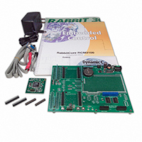
KIT DEV RABBIT3000/RCM3100
Manufacturer
Rabbit Semiconductor
Series
RabbitCore 3000r
Type
MPU Moduler
Datasheet
1.101-0517.pdf
(110 pages)
Specifications of 101-0533
Rohs Status
RoHS non-compliant
Contents
RabbitCore Module, Dev. Board, AC Adapter, Cable and Dynamic C® CD-Rom
Processor To Be Evaluated
RCM3100
Interface Type
RS-232, Ethernet
Maximum Operating Temperature
+ 85 C
Minimum Operating Temperature
- 40 C
Operating Supply Voltage
3.15 V to 3.45 V
For Use With/related Products
RCM3100
Lead Free Status / Rohs Status
Lead free / RoHS Compliant
Other names
316-1020


B.1.1 Prototyping Board Features
•
•
•
•
•
•
•
•
•
User’s Manual
Power Connection
nection to the power supply. Note that the 3-pin header is symmetrical, with both outer
pins connected to ground and the center pin connected to the raw V+ input. The cable
of the AC adapter provided with the North American version of the Development Kit
ends in a plug that connects to the power-supply jack. The header plug leading to bare
leads provided for overseas customers can be connected to the 3-pin header in either
orientation.
Users providing their own power supply should ensure that it delivers 8–24 V DC at
8 W. The voltage regulators will get warm while in use.
Regulated Power Supply
routed to a 5 V switching voltage regulator, then to a separate 3.3 V linear regulator.
The regulators provide stable power to the RCM3100 module and the Prototyping
Board.
Power LED
Board.
Reset Switch
RCM3100’s
I/O Switches and LEDs
nected to the PG0 and PG1 pins of the master RCM3100 module and may be read as
inputs by sample applications.
Two LEDs are connected to the PG6 and PG7 pins of the master module, and may be
driven as output indicators by sample applications.
Prototyping Area
of through-hole components. +3.3 V, +5 V, and Ground buses run around the edge of
this area. Several areas for surface-mount devices are also available. (Note that there
are SMT device pads on both top and bottom of the Prototyping Board.) Each SMT pad
is connected to a hole designed to accept a 30 AWG solid wire.
Master Module Connectors
of the first RCM3000, RCM3100, or RCM3200 module that serves as the primary or
“master module.”
Slave Module Connectors
lation of a second, slave RCM3000, RCM3100, or RCM3200 module. This capability
is reserved for future use, although the schematics in this manual contain all of the
details an experienced developer will need to implement a master-slave system.
Module Extension Headers
SLAVE
can solder wires directly into the appropriate holes, or, for more flexible development,
26-pin header strips can be soldered into place. See Figure B-4 for the header pinouts.
RabbitCore modules are duplicated at these two sets of headers. Developers
—The power LED lights whenever power is connected to the Prototyping
/RESET_IN
—A momentary-contact, normally open switch is connected directly to the
—A generous prototyping area has been provided for the installation
—A power-supply jack and a 3-pin header are provided for con-
pin. Pressing the switch forces a hardware reset of the system.
—Two momentary-contact, normally open switches are con-
—The raw DC voltage provided at the POWER IN jack is
—A second set of connectors is pre-wired to permit instal-
—The complete pin sets of both the
—A set of connectors is pre-wired to permit installation
MASTER
and
47
Related parts for 101-0533
Image
Part Number
Description
Manufacturer
Datasheet
Request
R

Part Number:
Description:
COMPUTER SNGLBD BL2101 A/D 0-10V
Manufacturer:
Rabbit Semiconductor
Part Number:
Description:
CARD D/A 0-10V SR9400 SMARTSTAR
Manufacturer:
Rabbit Semiconductor
Datasheet:
Part Number:
Description:
CARD A/D 0-10V SR9300 SMARTSTAR
Manufacturer:
Rabbit Semiconductor
Datasheet:

Part Number:
Description:
WiFi / 802.11 Modules & Development Tools WIRELESS CONTROL APP KIT
Manufacturer:
Rabbit Semiconductor

Part Number:
Description:
KIT DEV RABBITCORE RCM3750
Manufacturer:
Rabbit Semiconductor
Datasheet:
Part Number:
Description:
KIT DEV RABBIT 2000 INT'L
Manufacturer:
Rabbit Semiconductor
Datasheet:
Part Number:
Description:
KIT DEV RABBIT RCM2000 INT'L
Manufacturer:
Rabbit Semiconductor
Datasheet:

Part Number:
Description:
KIT DEVELOPMENT RCM3700 INT'L
Manufacturer:
Rabbit Semiconductor
Datasheet:

Part Number:
Description:
BL4S200 TOOL KIT
Manufacturer:
Rabbit Semiconductor
Datasheet:
Part Number:
Description:
MODULE RABBITCORE RCM3720
Manufacturer:
Rabbit Semiconductor
Datasheet:
Part Number:
Description:
MODULE RABBITCORE RCM3220
Manufacturer:
Rabbit Semiconductor
Datasheet:
Part Number:
Description:
MODULE RABBITCORE RCM3210
Manufacturer:
Rabbit Semiconductor
Datasheet:
Part Number:
Description:
COMPUTER SGL-BOARD OP6600 W/SRAM
Manufacturer:
Rabbit Semiconductor
Datasheet:
Part Number:
Description:
COMPUTER SGL-BD BL2000 SRAM/FLSH
Manufacturer:
Rabbit Semiconductor