101-0533 Rabbit Semiconductor, 101-0533 Datasheet - Page 4
101-0533
Manufacturer Part Number
101-0533
Description
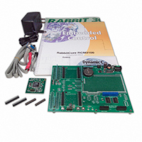
KIT DEV RABBIT3000/RCM3100
Manufacturer
Rabbit Semiconductor
Series
RabbitCore 3000r
Type
MPU Moduler
Datasheet
1.101-0517.pdf
(110 pages)
Specifications of 101-0533
Rohs Status
RoHS non-compliant
Contents
RabbitCore Module, Dev. Board, AC Adapter, Cable and Dynamic C® CD-Rom
Processor To Be Evaluated
RCM3100
Interface Type
RS-232, Ethernet
Maximum Operating Temperature
+ 85 C
Minimum Operating Temperature
- 40 C
Operating Supply Voltage
3.15 V to 3.45 V
For Use With/related Products
RCM3100
Lead Free Status / Rohs Status
Lead free / RoHS Compliant
Other names
316-1020


Chapter 5. Software Reference
Appendix A. RabbitCore RCM3100 Specifications
Appendix B. Prototyping Board
Appendix C. LCD/Keypad Module
Appendix D. Power Supply
5.1 More About Dynamic C ..................................................................................................................... 29
5.2 Dynamic C Function Calls ................................................................................................................ 31
5.3 Upgrading Dynamic C ....................................................................................................................... 32
A.1 Electrical and Mechanical Characteristics ........................................................................................ 34
A.2 Bus Loading ...................................................................................................................................... 38
A.3 Rabbit 3000 DC Characteristics ........................................................................................................ 41
A.4 I/O Buffer Sourcing and Sinking Limit............................................................................................. 42
A.5 Conformal Coating ............................................................................................................................ 43
A.6 Jumper Configurations ...................................................................................................................... 44
B.1 Introduction ....................................................................................................................................... 46
B.2 Mechanical Dimensions and Layout ................................................................................................. 49
B.3 Power Supply..................................................................................................................................... 50
B.4 Using the Prototyping Board ............................................................................................................. 51
B.5 Use of Rabbit 3000 Parallel Ports...................................................................................................... 54
C.1 Specifications..................................................................................................................................... 57
C.2 Contrast Adjustments for All Boards ................................................................................................ 59
C.3 Keypad Labeling................................................................................................................................ 60
C.4 Header Pinouts................................................................................................................................... 61
C.5 Mounting LCD/Keypad Module on the Prototyping Board.............................................................. 62
C.6 Bezel-Mount Installation ................................................................................................................... 63
C.7 LCD/Keypad Module Function Calls................................................................................................ 66
C.8 Sample Programs............................................................................................................................... 85
D.1 Power Supplies .................................................................................................................................. 87
5.2.1 I/O............................................................................................................................................... 31
5.2.2 Serial Communication Drivers ................................................................................................... 31
5.2.3 Prototyping Board Functions...................................................................................................... 31
5.3.1 Upgrades..................................................................................................................................... 32
A.1.1 Exclusion Zone .......................................................................................................................... 36
A.1.2 Headers ...................................................................................................................................... 37
A.1.3 Physical Mounting..................................................................................................................... 37
B.1.1 Prototyping Board Features ....................................................................................................... 47
B.4.1 Adding Other Components ........................................................................................................ 52
B.4.2 Measuring Current Draw ........................................................................................................... 52
B.4.3 Other Prototyping Board Modules and Options ........................................................................ 53
C.4.1 I/O Address Assignments .......................................................................................................... 61
C.6.1 Connect the LCD/Keypad Module to Your Prototyping Board ................................................ 65
C.7.1 LCD/Keypad Module Initialization ........................................................................................... 66
C.7.2 LEDs .......................................................................................................................................... 66
C.7.3 LCD Display .............................................................................................................................. 67
C.7.4 Keypad ....................................................................................................................................... 82
D.1.1 Battery-Backup Circuits ............................................................................................................ 87
D.1.2 Reset Generator ......................................................................................................................... 88
5.2.3.1 Board Initialization ............................................................................................................ 31
RabbitCore RCM3100
29
33
45
57
87
Related parts for 101-0533
Image
Part Number
Description
Manufacturer
Datasheet
Request
R

Part Number:
Description:
COMPUTER SNGLBD BL2101 A/D 0-10V
Manufacturer:
Rabbit Semiconductor
Part Number:
Description:
CARD D/A 0-10V SR9400 SMARTSTAR
Manufacturer:
Rabbit Semiconductor
Datasheet:
Part Number:
Description:
CARD A/D 0-10V SR9300 SMARTSTAR
Manufacturer:
Rabbit Semiconductor
Datasheet:

Part Number:
Description:
WiFi / 802.11 Modules & Development Tools WIRELESS CONTROL APP KIT
Manufacturer:
Rabbit Semiconductor

Part Number:
Description:
KIT DEV RABBITCORE RCM3750
Manufacturer:
Rabbit Semiconductor
Datasheet:
Part Number:
Description:
KIT DEV RABBIT 2000 INT'L
Manufacturer:
Rabbit Semiconductor
Datasheet:
Part Number:
Description:
KIT DEV RABBIT RCM2000 INT'L
Manufacturer:
Rabbit Semiconductor
Datasheet:

Part Number:
Description:
KIT DEVELOPMENT RCM3700 INT'L
Manufacturer:
Rabbit Semiconductor
Datasheet:

Part Number:
Description:
BL4S200 TOOL KIT
Manufacturer:
Rabbit Semiconductor
Datasheet:
Part Number:
Description:
MODULE RABBITCORE RCM3720
Manufacturer:
Rabbit Semiconductor
Datasheet:
Part Number:
Description:
MODULE RABBITCORE RCM3220
Manufacturer:
Rabbit Semiconductor
Datasheet:
Part Number:
Description:
MODULE RABBITCORE RCM3210
Manufacturer:
Rabbit Semiconductor
Datasheet:
Part Number:
Description:
COMPUTER SGL-BOARD OP6600 W/SRAM
Manufacturer:
Rabbit Semiconductor
Datasheet:
Part Number:
Description:
COMPUTER SGL-BD BL2000 SRAM/FLSH
Manufacturer:
Rabbit Semiconductor