101-0533 Rabbit Semiconductor, 101-0533 Datasheet - Page 18
101-0533
Manufacturer Part Number
101-0533
Description
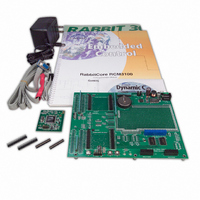
KIT DEV RABBIT3000/RCM3100
Manufacturer
Rabbit Semiconductor
Series
RabbitCore 3000r
Type
MPU Moduler
Datasheet
1.101-0517.pdf
(110 pages)
Specifications of 101-0533
Rohs Status
RoHS non-compliant
Contents
RabbitCore Module, Dev. Board, AC Adapter, Cable and Dynamic C® CD-Rom
Processor To Be Evaluated
RCM3100
Interface Type
RS-232, Ethernet
Maximum Operating Temperature
+ 85 C
Minimum Operating Temperature
- 40 C
Operating Supply Voltage
3.15 V to 3.45 V
For Use With/related Products
RCM3100
Lead Free Status / Rohs Status
Lead free / RoHS Compliant
Other names
316-1020


3.2 Sample Programs
Of the many sample programs included with Dynamic C, several are specific to the
RCM3100. Sample programs illustrating the general operation of the RCM3100, and
serial communication are provided in the
has comments that describe the purpose and function of the program. Follow the instruc-
tions at the beginning of the sample program.
•
•
•
•
•
Once you have loaded and executed these sample programs and have an understanding of
how Dynamic C and the RCM3100 modules interact, you can move on and try the other
sample programs, or begin building your own.
12
CONTROLLED.C
LEDs DS1 and DS2 on the Prototyping Board on and off.
Parallel Port G bit 6 = LED DS1
Parallel Port G bit 7 = LED DS2
Once you have compiled and run this program, you will be prompted via the Dynamic C
STDIO
selection.
Once you have selected the LED, you will be prompted to select to turn the LED either
ON or OFF. A logic low will light up the LED you selected.
FLASHLED1.c
the Prototyping Board at different rates. Once you have compiled and run this program,
LEDs DS1 and DS2 will flash on/off at different rates.
FLASHLED2.c
DS1 and DS2 on the Prototyping Board at different rates. Once you have compiled and
run this program, LEDs DS1 and DS2 will flash on/off at different rates.
TOGGLESWITCH.c
press-and-release method of debouncing. LEDs DS1 and DS2 on the Prototyping
Board are turned on and off when you press switches S2 and S3.
IR_DEMO.c
Board assemblies via the IrDA transceivers with the IrDA transceivers facing each other.
Note that this sample program will only work with the RCM30/31/32XX Prototyping
Board.
First, compile and run this program on one Prototyping Board assembly, then remove
the programming cable and press the
the first RabbitCore module is operating in the
ming cable to the second Prototyping Board assembly with the RCM3100 and compile
and run the same sample program. With the programming cable still connected to the
second Prototyping Board assembly, press switch S2 on the second Prototyping Board
to transmit a packet. Once the first Prototyping Board assembly receives a test packet, it
will send back a response packet that will be displayed in the Dynamic C
dow. The test packets and response packets have different codes.
window to select LED DS1 or DS2. Use your PC keyboard to make your
—Demonstrates sending Modbus ASCII packets between two Prototyping
—demonstrates the use of costatements to flash LEDs DS1 and DS2 on
—demonstrates the use of cofunctions and costatements to flash LEDs
—uses the
—demonstrates the use of costatements to detect switches using the
STDIO
window to demonstrate digital outputs by toggling
RESET
SAMPLES\RCM3100
button on the Prototyping Board so that
Run
mode. Then connect the program-
folder. Each sample program
RabbitCore RCM3100
STDIO
win-
Related parts for 101-0533
Image
Part Number
Description
Manufacturer
Datasheet
Request
R

Part Number:
Description:
COMPUTER SNGLBD BL2101 A/D 0-10V
Manufacturer:
Rabbit Semiconductor
Part Number:
Description:
CARD D/A 0-10V SR9400 SMARTSTAR
Manufacturer:
Rabbit Semiconductor
Datasheet:
Part Number:
Description:
CARD A/D 0-10V SR9300 SMARTSTAR
Manufacturer:
Rabbit Semiconductor
Datasheet:

Part Number:
Description:
WiFi / 802.11 Modules & Development Tools WIRELESS CONTROL APP KIT
Manufacturer:
Rabbit Semiconductor

Part Number:
Description:
KIT DEV RABBITCORE RCM3750
Manufacturer:
Rabbit Semiconductor
Datasheet:
Part Number:
Description:
KIT DEV RABBIT 2000 INT'L
Manufacturer:
Rabbit Semiconductor
Datasheet:
Part Number:
Description:
KIT DEV RABBIT RCM2000 INT'L
Manufacturer:
Rabbit Semiconductor
Datasheet:

Part Number:
Description:
KIT DEVELOPMENT RCM3700 INT'L
Manufacturer:
Rabbit Semiconductor
Datasheet:

Part Number:
Description:
BL4S200 TOOL KIT
Manufacturer:
Rabbit Semiconductor
Datasheet:
Part Number:
Description:
MODULE RABBITCORE RCM3720
Manufacturer:
Rabbit Semiconductor
Datasheet:
Part Number:
Description:
MODULE RABBITCORE RCM3220
Manufacturer:
Rabbit Semiconductor
Datasheet:
Part Number:
Description:
MODULE RABBITCORE RCM3210
Manufacturer:
Rabbit Semiconductor
Datasheet:
Part Number:
Description:
COMPUTER SGL-BOARD OP6600 W/SRAM
Manufacturer:
Rabbit Semiconductor
Datasheet:
Part Number:
Description:
COMPUTER SGL-BD BL2000 SRAM/FLSH
Manufacturer:
Rabbit Semiconductor