DEMO9S12XEP100 Freescale Semiconductor, DEMO9S12XEP100 Datasheet - Page 707
DEMO9S12XEP100
Manufacturer Part Number
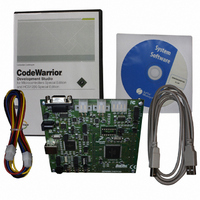
DEMO9S12XEP100
Description
BOARD DEMO FOR MC9S12XEP100
Manufacturer
Freescale Semiconductor
Type
MCUr
Datasheet
1.EVB9S12XEP100.pdf
(1328 pages)
Specifications of DEMO9S12XEP100
Contents
Board, Cables, CD
Processor To Be Evaluated
MC9S12XEP100
Data Bus Width
16 bit
Interface Type
RS-232
Silicon Manufacturer
Freescale
Core Architecture
S12
Core Sub-architecture
S12
Silicon Core Number
MC9S12
Silicon Family Name
S12XE
Rohs Compliant
Yes
For Use With/related Products
MC9S12XEP100
Lead Free Status / RoHS Status
Lead free / RoHS Compliant
Available stocks
Company
Part Number
Manufacturer
Quantity
Price
Company:

Part Number:
DEMO9S12XEP100
Manufacturer:
PANASONIC
Quantity:
46 000
Company:
Part Number:
DEMO9S12XEP100
Manufacturer:
Freescale Semiconductor
Quantity:
135


Read: Anytime
Write: Anytime (causes the scale counter to load the PWMSCLB value).
19.3.2.11 Reserved Registers (PWMSCNTx)
The registers PWMSCNTA and PWMSCNTB are reserved for factory testing of the PWM module and are
not available in normal modes.
Read: Always read $00 in normal modes
Write: Unimplemented in normal modes
19.3.2.12 PWM Channel Counter Registers (PWMCNTx)
Each channel has a dedicated 8-bit up/down counter which runs at the rate of the selected clock source.
The counter can be read at any time without affecting the count or the operation of the PWM channel. In
left aligned output mode, the counter counts from 0 to the value in the period register - 1. In center aligned
output mode, the counter counts from 0 up to the value in the period register and then back down to 0.
Any value written to the counter causes the counter to reset to $00, the counter direction to be set to up,
the immediate load of both duty and period registers with values from the buffers, and the output to change
according to the polarity bit. The counter is also cleared at the end of the effective period (see
Section 19.4.2.5, “Left Aligned Outputs”
details). When the channel is disabled (PWMEx = 0), the PWMCNTx register does not count. When a
channel becomes enabled (PWMEx = 1), the associated PWM counter starts at the count in the
PWMCNTx register. For more detailed information on the operation of the counters, see
“PWM Timer
In concatenated mode, writes to the 16-bit counter by using a 16-bit access or writes to either the low or
high order byte of the counter will reset the 16-bit counter. Reads of the 16-bit counter must be made by
16-bit access to maintain data coherency.
Freescale Semiconductor
Module Base + 0x000A, 0x000B
Because of an order from the United States International Trade Commission, BGA-packaged product lines and partnumbers
Reset
indicated here currently are not available from Freescale for import or sale in the United States prior to September 2010
W
R
0
0
7
Counters”.
Writing to these registers when in special modes can alter the PWM
functionality.
= Unimplemented or Reserved
0
0
6
Figure 19-13. Reserved Registers (PWMSCNTx)
MC9S12XE-Family Reference Manual Rev. 1.23
5
0
0
and
Section 19.4.2.6, “Center Aligned Outputs”
NOTE
0
0
4
0
0
3
Chapter 19 Pulse-Width Modulator (S12PWM8B8CV1)
2
0
0
0
0
1
Section 19.4.2.4,
for more
0
0
0
707
Related parts for DEMO9S12XEP100
Image
Part Number
Description
Manufacturer
Datasheet
Request
R

Part Number:
Description:
Manufacturer:
Freescale Semiconductor, Inc
Datasheet:
Part Number:
Description:
Manufacturer:
Freescale Semiconductor, Inc
Datasheet:
Part Number:
Description:
Manufacturer:
Freescale Semiconductor, Inc
Datasheet:
Part Number:
Description:
Manufacturer:
Freescale Semiconductor, Inc
Datasheet:
Part Number:
Description:
Manufacturer:
Freescale Semiconductor, Inc
Datasheet:
Part Number:
Description:
Manufacturer:
Freescale Semiconductor, Inc
Datasheet:
Part Number:
Description:
Manufacturer:
Freescale Semiconductor, Inc
Datasheet:
Part Number:
Description:
Manufacturer:
Freescale Semiconductor, Inc
Datasheet:
Part Number:
Description:
Manufacturer:
Freescale Semiconductor, Inc
Datasheet:
Part Number:
Description:
Manufacturer:
Freescale Semiconductor, Inc
Datasheet:
Part Number:
Description:
Manufacturer:
Freescale Semiconductor, Inc
Datasheet:
Part Number:
Description:
Manufacturer:
Freescale Semiconductor, Inc
Datasheet:
Part Number:
Description:
Manufacturer:
Freescale Semiconductor, Inc
Datasheet:
Part Number:
Description:
Manufacturer:
Freescale Semiconductor, Inc
Datasheet:
Part Number:
Description:
Manufacturer:
Freescale Semiconductor, Inc
Datasheet: