DEMO9S12XEP100 Freescale Semiconductor, DEMO9S12XEP100 Datasheet - Page 334
DEMO9S12XEP100
Manufacturer Part Number
DEMO9S12XEP100
Description
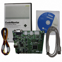
BOARD DEMO FOR MC9S12XEP100
Manufacturer
Freescale Semiconductor
Type
MCUr
Datasheet
1.EVB9S12XEP100.pdf
(1328 pages)
Specifications of DEMO9S12XEP100
Contents
Board, Cables, CD
Processor To Be Evaluated
MC9S12XEP100
Data Bus Width
16 bit
Interface Type
RS-232
Silicon Manufacturer
Freescale
Core Architecture
S12
Core Sub-architecture
S12
Silicon Core Number
MC9S12
Silicon Family Name
S12XE
Rohs Compliant
Yes
For Use With/related Products
MC9S12XEP100
Lead Free Status / RoHS Status
Lead free / RoHS Compliant
Available stocks
Company
Part Number
Manufacturer
Quantity
Price
Company:

Part Number:
DEMO9S12XEP100
Manufacturer:
PANASONIC
Quantity:
46 000
Company:
Part Number:
DEMO9S12XEP100
Manufacturer:
Freescale Semiconductor
Quantity:
135


Chapter 8 S12X Debug (S12XDBGV3) Module
this triggers the state sequencer into the Final State, if configured for end alignment, setting the TRIG bit
disarms the module, ending the session. If breakpoints are enabled, a forced breakpoint request is issued
immediately (end alignment) or when tracing has completed (begin or mid alignment).
8.4.3.6
In case of simultaneous triggers, the priority is resolved according to
is suppressed. It is thus possible to miss a lower priority trigger if it occurs simultaneously with a trigger
of a higher priority. The trigger priorities described in
matches, the match on the lower channel number (0,1,2,3) has priority. The SC[3:0] encoding ensures that
a match leading to final state has priority over all other matches in each state sequencer state. When
configured for range modes a simultaneous match of comparators A and C generates an active match0
whilst match2 is suppressed.
If a write access to DBGC1 with the ARM bit position set occurs simultaneously to a hardware disarm
from an internal trigger event, then the ARM bit is cleared due to the hardware disarm.
8.4.4
The state sequencer allows a defined sequence of events to provide a trigger point for tracing of data in the
trace buffer. Once the S12XDBG module has been armed by setting the ARM bit in the DBGC1 register,
334
Because of an order from the United States International Trade Commission, BGA-packaged product lines and partnumbers
indicated here currently are not available from Freescale for import or sale in the United States prior to September 2010
Highest
Priority
Lowest
State Sequence Control
Trigger Priorities
(Disarmed)
Match0 (force or tag hit)
Match1 (force or tag hit)
Match2 (force or tag hit)
Match3 (force or tag hit)
State 0
ARM = 0
External TAGHI/TAGLO
XGATE BKP
Source
ARM = 0
TRIG
Session Complete
MC9S12XE-Family Reference Manual , Rev. 1.23
(Disarm)
ARM = 1
ARM = 0
Figure 8-22. State Sequencer Diagram
Table 8-42. Trigger Priorities
Trigger immediately to final state (begin or mid aligned tracing enabled)
Immediate forced breakpoint......(Tracing terminated immediately).
Trigger immediately to state 0 (end aligned or no tracing enabled)
Final State
Trigger to next state as defined by state control registers
Trigger to next state as defined by state control registers
Trigger to next state as defined by state control registers
Trigger to next state as defined by state control registers
Table 8-42
State1
dictate that in the case of simultaneous
Table
Enter State0
State3
Action
8-42. The lower priority trigger
State2
Freescale Semiconductor
Related parts for DEMO9S12XEP100
Image
Part Number
Description
Manufacturer
Datasheet
Request
R

Part Number:
Description:
Manufacturer:
Freescale Semiconductor, Inc
Datasheet:
Part Number:
Description:
Manufacturer:
Freescale Semiconductor, Inc
Datasheet:
Part Number:
Description:
Manufacturer:
Freescale Semiconductor, Inc
Datasheet:
Part Number:
Description:
Manufacturer:
Freescale Semiconductor, Inc
Datasheet:
Part Number:
Description:
Manufacturer:
Freescale Semiconductor, Inc
Datasheet:
Part Number:
Description:
Manufacturer:
Freescale Semiconductor, Inc
Datasheet:
Part Number:
Description:
Manufacturer:
Freescale Semiconductor, Inc
Datasheet:
Part Number:
Description:
Manufacturer:
Freescale Semiconductor, Inc
Datasheet:
Part Number:
Description:
Manufacturer:
Freescale Semiconductor, Inc
Datasheet:
Part Number:
Description:
Manufacturer:
Freescale Semiconductor, Inc
Datasheet:
Part Number:
Description:
Manufacturer:
Freescale Semiconductor, Inc
Datasheet:
Part Number:
Description:
Manufacturer:
Freescale Semiconductor, Inc
Datasheet:
Part Number:
Description:
Manufacturer:
Freescale Semiconductor, Inc
Datasheet:
Part Number:
Description:
Manufacturer:
Freescale Semiconductor, Inc
Datasheet:
Part Number:
Description:
Manufacturer:
Freescale Semiconductor, Inc
Datasheet: