101-1108 Rabbit Semiconductor, 101-1108 Datasheet - Page 55
101-1108
Manufacturer Part Number
101-1108
Description
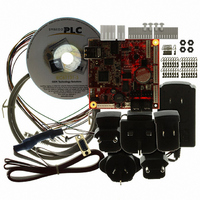
KIT EMBEDDED PLC APPLICATION
Manufacturer
Rabbit Semiconductor
Series
Coyoter
Type
MPU Moduler
Datasheet
1.101-1108.pdf
(70 pages)
Specifications of 101-1108
Contents
BL2500, ISaGRAF V3.50, Embedded PLC software kernel, ISaGRAF Programming Cable and Documentation
Processor To Be Evaluated
Rabbit 3000
Interface Type
RS-232, Ethernet
For Use With/related Products
BL2500
Lead Free Status / RoHS Status
Contains lead / RoHS non-compliant
Other names
316-1120


EMBEDDED
2. Connect the power supply to the BL2500 following the instructions in Section 2.4.1.
6.1.3 Loading and licensing the Firmware Kernel
The
BL2500C_BSP_V1.04_9-0003-006\Kernels directory of the CD-ROM (or in the ZIP file, if
downloaded from the website). It is recommended to copy this file from the CD-ROM to a local PC folder,
referred in this procedure as <EMBEDDED PLC Kernel Dir>. Use the following procedure to load the
EMBEDDED
1. Open the
2. Select File → Load Flash Image… from the main
4. After loading is completed a message dialog box is displayed. Follow the instructions in the same
OEM Technology Solutions
Select the serial COM port where the programming cable is connected. Check the Use USB to Serial
converter check-box if you have the RS232-to-USB converter cable. Press OK.
menu bar. On Choose Flash Image window press ...
button. On the Open window select the
PLC Firmware Kernel file <EMBEDDED PLC Kernel
Dir>\BL2500C_V1.04_3-0231H.bin and press
Open. Press OK on the Choose Flash Image
window.
order: Connect DIAG cable → Reset Target → Press OK. There are two ways to reset the BL2500:
EMBEDDED
PLC BL2500 User’s Manual
PLC Firmware Kernel to the Target:
EMBEDDED
PLC BL2500 Firmware Kernel file (BL2500C_V1.04_3-0231H.bin) is located in the
PLC Utility and select Setup → Communications… from the main menu bar.
Figure 12: Programming Cable Connection
EMBEDDED
3. A Progress window is displayed with the status of the
loading process. The process consists of four stages:
Sending Coldloader → Sending Pilot BIOS → Erasing
Flash → Sending Program.
Loading or Upgrading the Firmware Kernel
unplugging the power supply and then
plugging it again (also known as a
power cycle); and the other is shorting
out the reset pads on the back of the
BL2500 board. For more information
about the location of the hardware reset
see Section 2.2.1 in [1].
Page 49
Related parts for 101-1108
Image
Part Number
Description
Manufacturer
Datasheet
Request
R

Part Number:
Description:
KIT DEV FOR BL2500 COYOTE
Manufacturer:
Rabbit Semiconductor
Datasheet:

Part Number:
Description:
KIT APPLICATION SIMPLE SENSOR
Manufacturer:
Rabbit Semiconductor
Datasheet:

Part Number:
Description:
KIT DEV RABBITCORE RCM3750
Manufacturer:
Rabbit Semiconductor
Datasheet:

Part Number:
Description:
KIT DEV RABBIT 2000 INT'L
Manufacturer:
Rabbit Semiconductor
Datasheet:
Part Number:
Description:
KIT DEV RABBIT RCM2000 INT'L
Manufacturer:
Rabbit Semiconductor
Datasheet:

Part Number:
Description:
KIT DEVELOPMENT RCM3700 INT'L
Manufacturer:
Rabbit Semiconductor
Datasheet:

Part Number:
Description:
BL4S200 TOOL KIT
Manufacturer:
Rabbit Semiconductor
Datasheet:


Part Number:
Description:
KIT DEVELOPMENT FOR JACKRABBIT
Manufacturer:
Rabbit Semiconductor
Part Number:
Description:
MODULE RABBITCORE RCM3720
Manufacturer:
Rabbit Semiconductor
Datasheet:
Part Number:
Description:
MODULE RABBITCORE RCM3220
Manufacturer:
Rabbit Semiconductor
Datasheet:
Part Number:
Description:
MODULE RABBITCORE RCM3210
Manufacturer:
Rabbit Semiconductor
Datasheet:
Part Number:
Description:
COMPUTER SGL-BOARD OP6600 W/SRAM
Manufacturer:
Rabbit Semiconductor
Datasheet:
Part Number:
Description:
COMPUTER SGL-BD BL2000 SRAM/FLSH
Manufacturer:
Rabbit Semiconductor