101-1108 Rabbit Semiconductor, 101-1108 Datasheet - Page 34
101-1108
Manufacturer Part Number
101-1108
Description
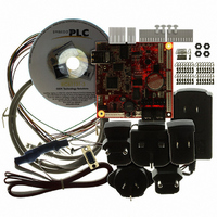
KIT EMBEDDED PLC APPLICATION
Manufacturer
Rabbit Semiconductor
Series
Coyoter
Type
MPU Moduler
Datasheet
1.101-1108.pdf
(70 pages)
Specifications of 101-1108
Contents
BL2500, ISaGRAF V3.50, Embedded PLC software kernel, ISaGRAF Programming Cable and Documentation
Processor To Be Evaluated
Rabbit 3000
Interface Type
RS-232, Ethernet
For Use With/related Products
BL2500
Lead Free Status / RoHS Status
Contains lead / RoHS non-compliant
Other names
316-1120


EMBEDDED
6. Follow Steps 6 to 11 in 3.4.1 to create and populate the application’s Dictionary with SW1 and SW2
7. On the B25TEST3 – Programs window double-click on STtest1 program.
8. Type in a comment in comment parentheses (* *) such as (* Exclusive OR logic for switching on
9. Press Enter to move to the next command line in the ST program editor.
10. To enter Keyword commands, either click the desired button in the Keywords tool box or type it,
11. To enter inputs, outputs, or variables, for example input switch SW1, either select Edit → Insert
12. Type the following command lines under the entered comment:
13. The LDtest1 program should now appear as follows:
14. Save the program by selecting File menu → Save. Press OK button on the Update diary window.
15. Follow Steps 17 to 25 in 3.4.1 to compile the application and download it to the Target PLC.
16. Double-click on STtest1 program. The STTEST1 – ST Programs window is displayed. Press the
17. To stop the monitoring of the PLC application, close the Debugger window. The programs and
OEM Technology Solutions
Boolean input variables, and LED1 Boolean output variable.
LED *). When entered correctly comments are highlighted green.
such as for an ‘if’ statement, either click IF in the Keyword tool box or type IF on the command line.
When correctly entered Keyword commands are highlighted pink.
variable → SW1 or type SW1 on the command line.
Close the STtest1 – ST Program window.
SW1 (short-circuit digital input IN00) and the LED1 will be turned ON as well as the state of LED1 in
the Programs window will change. The PLC program implements a Boolean XOR operation on SW1
and SW2 with the result set on the LED1.
dictionary windows in debug mode will be closed.
IF SW1 = SW2
THEN
ELSE
END_IF;
PLC BL2500 User’s Manual
LED1 := FALSE;
LED1 := TRUE;
Running Sample Applications
Page 28
Related parts for 101-1108
Image
Part Number
Description
Manufacturer
Datasheet
Request
R

Part Number:
Description:
KIT DEV FOR BL2500 COYOTE
Manufacturer:
Rabbit Semiconductor
Datasheet:

Part Number:
Description:
KIT APPLICATION SIMPLE SENSOR
Manufacturer:
Rabbit Semiconductor
Datasheet:

Part Number:
Description:
KIT DEV RABBITCORE RCM3750
Manufacturer:
Rabbit Semiconductor
Datasheet:

Part Number:
Description:
KIT DEV RABBIT 2000 INT'L
Manufacturer:
Rabbit Semiconductor
Datasheet:
Part Number:
Description:
KIT DEV RABBIT RCM2000 INT'L
Manufacturer:
Rabbit Semiconductor
Datasheet:

Part Number:
Description:
KIT DEVELOPMENT RCM3700 INT'L
Manufacturer:
Rabbit Semiconductor
Datasheet:

Part Number:
Description:
BL4S200 TOOL KIT
Manufacturer:
Rabbit Semiconductor
Datasheet:


Part Number:
Description:
KIT DEVELOPMENT FOR JACKRABBIT
Manufacturer:
Rabbit Semiconductor
Part Number:
Description:
MODULE RABBITCORE RCM3720
Manufacturer:
Rabbit Semiconductor
Datasheet:
Part Number:
Description:
MODULE RABBITCORE RCM3220
Manufacturer:
Rabbit Semiconductor
Datasheet:
Part Number:
Description:
MODULE RABBITCORE RCM3210
Manufacturer:
Rabbit Semiconductor
Datasheet:
Part Number:
Description:
COMPUTER SGL-BOARD OP6600 W/SRAM
Manufacturer:
Rabbit Semiconductor
Datasheet:
Part Number:
Description:
COMPUTER SGL-BD BL2000 SRAM/FLSH
Manufacturer:
Rabbit Semiconductor