101-1108 Rabbit Semiconductor, 101-1108 Datasheet - Page 39
101-1108
Manufacturer Part Number
101-1108
Description
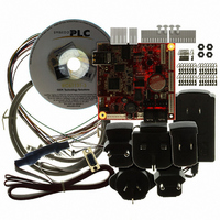
KIT EMBEDDED PLC APPLICATION
Manufacturer
Rabbit Semiconductor
Series
Coyoter
Type
MPU Moduler
Datasheet
1.101-1108.pdf
(70 pages)
Specifications of 101-1108
Contents
BL2500, ISaGRAF V3.50, Embedded PLC software kernel, ISaGRAF Programming Cable and Documentation
Processor To Be Evaluated
Rabbit 3000
Interface Type
RS-232, Ethernet
For Use With/related Products
BL2500
Lead Free Status / RoHS Status
Contains lead / RoHS non-compliant
Other names
316-1120


EMBEDDED
3.4.6 Using Flow Chart
1. Open the ISaGRAF Project Management by double-clicking on the ISaGRAF Projects icon on your
2. On the Create new project window, enter the
3. Select Edit menu → Set comment text. Enter a brief description of this project and press OK button.
4. Double-click on b25test6 project. An empty B25TEST6 – Programs window is displayed.
6. Follow Steps 6 to 11 in 3.4.1 to create and populate the application’s Dictionary with SW1 and SW2
7. On the B25TEST6 – Programs window double-click on FCtest1 program.
8. Select the Insert a comment button
9. Select the Insert a test button
10. Select the Insert an action button
OEM Technology Solutions
Desktop or selecting Start menu → Programs → ISaGRAF 3.5 → Projects. On the Projects
Management window, select File menu → New.
name of the project (for example b25test6) and
press OK button. The name of project should not
exceed 8 characters. The b25test6 project is then
listed in the Projects Management window.
This description will be displayed next to the project name in the Projects Management window.
Boolean input variables, and LED1 Boolean output variable.
editor. Double click on the box to type in a comment such as “Exclusive OR logic for switching on
LED”.
Double click on it to display the editing box for that symbol. Rename it SW1 = SW2, and type in the
code SW1 = SW2.
Double click on the action symbol placed on the “Yes” flow link to display the editing box. Rename it
LED1_OFF and type in the code:
Double click on the action symbol placed on the “No” flow link to display the editing box. Rename it
LED1_ON and type in the code:
PLC BL2500 User’s Manual
LED1 := FALSE;
LED1 := TRUE;
and place it between the “Begin” symbol and the “End” symbol.
5. Select File menu → New. On the New program window
and place one on each of the two flow links from the test.
and place the comment box in the FCtest1 Flow Chart
enter the name of the program (for example, FCtest1); a
brief comment; select the Language to FC; select Begin
Style and press OK button. The FCtest1 program is
displayed in the B25TEST6 – Programs window.
Running Sample Applications
Page 33
Related parts for 101-1108
Image
Part Number
Description
Manufacturer
Datasheet
Request
R

Part Number:
Description:
KIT DEV FOR BL2500 COYOTE
Manufacturer:
Rabbit Semiconductor
Datasheet:

Part Number:
Description:
KIT APPLICATION SIMPLE SENSOR
Manufacturer:
Rabbit Semiconductor
Datasheet:

Part Number:
Description:
KIT DEV RABBITCORE RCM3750
Manufacturer:
Rabbit Semiconductor
Datasheet:

Part Number:
Description:
KIT DEV RABBIT 2000 INT'L
Manufacturer:
Rabbit Semiconductor
Datasheet:
Part Number:
Description:
KIT DEV RABBIT RCM2000 INT'L
Manufacturer:
Rabbit Semiconductor
Datasheet:

Part Number:
Description:
KIT DEVELOPMENT RCM3700 INT'L
Manufacturer:
Rabbit Semiconductor
Datasheet:

Part Number:
Description:
BL4S200 TOOL KIT
Manufacturer:
Rabbit Semiconductor
Datasheet:


Part Number:
Description:
KIT DEVELOPMENT FOR JACKRABBIT
Manufacturer:
Rabbit Semiconductor
Part Number:
Description:
MODULE RABBITCORE RCM3720
Manufacturer:
Rabbit Semiconductor
Datasheet:
Part Number:
Description:
MODULE RABBITCORE RCM3220
Manufacturer:
Rabbit Semiconductor
Datasheet:
Part Number:
Description:
MODULE RABBITCORE RCM3210
Manufacturer:
Rabbit Semiconductor
Datasheet:
Part Number:
Description:
COMPUTER SGL-BOARD OP6600 W/SRAM
Manufacturer:
Rabbit Semiconductor
Datasheet:
Part Number:
Description:
COMPUTER SGL-BD BL2000 SRAM/FLSH
Manufacturer:
Rabbit Semiconductor