DK-DEV-3SL150N Altera, DK-DEV-3SL150N Datasheet - Page 22
DK-DEV-3SL150N
Manufacturer Part Number
DK-DEV-3SL150N
Description
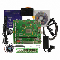
KIT DEVELOPMENT STRATIX III
Manufacturer
Altera
Series
Stratix® IIIr
Type
FPGAr
Datasheets
1.EP3SL150F780C4N.pdf
(16 pages)
2.EP3SL150F780C4N.pdf
(332 pages)
3.DK-DEV-3SL150N.pdf
(34 pages)
Specifications of DK-DEV-3SL150N
Contents
Development Platform, Cables and Software
Silicon Manufacturer
Altera
Core Architecture
FPGA
Core Sub-architecture
Stratix
Silicon Core Number
EP3S
Silicon Family Name
Stratix III
Kit Contents
Development Board, Cable And Accessories
Rohs Compliant
Yes
For Use With/related Products
EP3SL150F152
Lead Free Status / RoHS Status
Lead free / RoHS Compliant
Other names
544-2568
Available stocks
Company
Part Number
Manufacturer
Quantity
Price
Company:

Part Number:
DK-DEV-3SL150N
Manufacturer:
Altera
Quantity:
135


5–4
Measuring Voltage with a DMM
Calculating Power
Stratix III Development Kit User Guide
f
1
5. Using the user input push buttons
6. Press the User_PB3 button to enable the output pins on the HSMC connectors J8
7. Press the User_PB3 button again to disable the outputs. LED7 turns off.
8. Set the POWER SELECT rotary switch SW6 to 7.
9. Repeat steps
The sum of power results from the two sets of I/O banks provides the total FPGA I/O
power.
For specific information about on-board measurements and the POWER SELECT
rotary switch, refer to the
To obtain power values by using a DMM, measure voltage across the sense-resistors,
R215, R218, and R214 on the board, then use the voltage measurements to calculate
power.
For best results, use a DMM with six-digit or greater accuracy.
FPGA I/O power is distributed by banks
components R218 and R214. For the I/O power calculation, use the sum of voltage
measurements across these resistors while outputs are enabled. For the FPGA core
power calculation, measure the sense resistor voltage across R215.
Table 5–5. Sense Resistors
To obtain the power P in watts, measure the voltage across the sense resistors, V
and calculate the nominal power as follows:
If
power states in
as frequency and resources increase.
and J18. LED7 (E19), signal o_noutput_ena_state, lights to indicate that the
outputs are enabled and toggling. Enabling the outputs further increases power
for each resource utilization percentage used by the Stratix III FPGA.
V
I
V
R
SENSE
SENSE
SENSE
SUPPLY
I/O
= Current through the sense resistor
= Sense resistor value in
= Voltage measured across the sense resistor
= FPGA supply voltage
FPGA Power
Core: VCCL
4
through
Table 5–2
Banks 4, 5 and 6
Stratix III Development Board Reference
Bank 2
7
to observe the I/O output power in watts on bank 2.
and
Table 5–3 on page
Table
(Table 5–1 on page
5–5.
(Table
Voltage
2.5 V
2.5 V
1.1 V
5–5), for which the sense resistors are
5–2. Notice how power increases
5–1), advance through the
© August 2008 Altera Corporation
Resistor
Sense
R214
R218
R215
Chapter 5: Power Measurement
Manual.
Measuring Power
Resistor
0.009 Ω
0.009 Ω
0.009 Ω
Value
SENSE
,
Related parts for DK-DEV-3SL150N
Image
Part Number
Description
Manufacturer
Datasheet
Request
R

Part Number:
Description:
KIT DEV ARRIA II GX FPGA 2AGX125
Manufacturer:
Altera
Datasheet:

Part Number:
Description:
KIT DEV CYCLONE III LS EP3CLS200
Manufacturer:
Altera
Datasheet:

Part Number:
Description:
KIT DEV STRATIX IV FPGA 4SE530
Manufacturer:
Altera
Datasheet:

Part Number:
Description:
KIT DEV FPGA 2AGX260 W/6.375G TX
Manufacturer:
Altera
Datasheet:

Part Number:
Description:
KIT DEV MAX V 5M570Z
Manufacturer:
Altera
Datasheet:

Part Number:
Description:
KIT DEV STRATIX V FPGA 5SGXEA7
Manufacturer:
Altera
Datasheet:

Part Number:
Description:
KIT DEVELOPMENT STRATIX IV
Manufacturer:
Altera
Datasheet:

Part Number:
Description:
KIT DEV ARRIA GX 1AGX60N
Manufacturer:
Altera
Datasheet:
Part Number:
Description:
KIT STARTER CYCLONE IV GX
Manufacturer:
Altera
Datasheet:
Part Number:
Description:
KIT DEVELOPMENT STRATIX IV
Manufacturer:
Altera
Datasheet:

Part Number:
Description:
CPLD, EP610 Family, ECMOS Process, 300 Gates, 16 Macro Cells, 16 Reg., 16 User I/Os, 5V Supply, 35 Speed Grade, 24DIP
Manufacturer:
Altera Corporation
Datasheet:
Part Number:
Description:
CPLD, EP610 Family, ECMOS Process, 300 Gates, 16 Macro Cells, 16 Reg., 16 User I/Os, 5V Supply, 15 Speed Grade, 24DIP
Manufacturer:
Altera Corporation
Datasheet: