DK-DEV-3SL150N Altera, DK-DEV-3SL150N Datasheet - Page 17
DK-DEV-3SL150N
Manufacturer Part Number
DK-DEV-3SL150N
Description
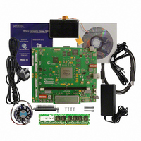
KIT DEVELOPMENT STRATIX III
Manufacturer
Altera
Series
Stratix® IIIr
Type
FPGAr
Datasheets
1.EP3SL150F780C4N.pdf
(16 pages)
2.EP3SL150F780C4N.pdf
(332 pages)
3.DK-DEV-3SL150N.pdf
(34 pages)
Specifications of DK-DEV-3SL150N
Contents
Development Platform, Cables and Software
Silicon Manufacturer
Altera
Core Architecture
FPGA
Core Sub-architecture
Stratix
Silicon Core Number
EP3S
Silicon Family Name
Stratix III
Kit Contents
Development Board, Cable And Accessories
Rohs Compliant
Yes
For Use With/related Products
EP3SL150F152
Lead Free Status / RoHS Status
Lead free / RoHS Compliant
Other names
544-2568
Available stocks
Company
Part Number
Manufacturer
Quantity
Price
Company:

Part Number:
DK-DEV-3SL150N
Manufacturer:
Altera
Quantity:
135


Chapter 4: Development Board Setup
Configuring the FPGA
Configuring the FPGA
© August 2008 Altera Corporation
f
f
w
Table 4–1. Switch SW2 Settings (Part 2 of 2)
4. Ensure that the 4-position SW1 mini-DIP switches and the two jumpers are set to
Table 4–2. Initial Switch and Jumper Settings
5. Ensure that the J13 MSEL0 GND jumper is ON.
6. Verify that the PGM CONFIG SELECT rotary switch SW3 is set to 0.
At power up, the development board uses a preloaded configuration to demonstrate
that the board is operating correctly.
Power up the development board by performing the following steps:
1. Connect the 16-V DC adapter to the development board and to a power source.
Use only the supplied 16-V power supply. Power regulation circuitry on the board
could be damaged by supplies greater than 16 V.
2. Slide the POWER switch to ON. The nearby blue POWER light-emitting diode
3. Confirm that user LEDs 0-7 flash in a scrolling, side-to-side pattern. For
For information about custom configurations, refer to
Device” on page
Before configuring the FPGA, ensure that the Quartus II software and the USB-Blaster
driver software are installed on the host computer and the development board is
powered on.
For USB-Blaster driver installation information, refer to
Driver” on page
Note to
(1) X = don’t care
DEV_SEL-J2
Switch
the default positions shown in
(LED) lights up.
customized configurations, the pattern depends on the application.
5
6
7
8
ON
Table
4–1:
MAX0
MAX1
MAX2
MAX3
JTAG_SEL-J3
3–3.
A–3.
Name
ON
SW1.1
PFL Disable
Table
ON
Position 0
4–2.
MAX_DIP1
MAX_DIP2
MAX_DIP3
Function
SW1.2
OFF
PFL Enable
“Programming the Flash
Position 1
“Installing the USB-Blaster
Stratix III Development Kit User Guide
SW1.3
OFF
Position
Default
SW1.4
1
X
X
X
OFF
4–3
Related parts for DK-DEV-3SL150N
Image
Part Number
Description
Manufacturer
Datasheet
Request
R

Part Number:
Description:
KIT DEV ARRIA II GX FPGA 2AGX125
Manufacturer:
Altera
Datasheet:

Part Number:
Description:
KIT DEV CYCLONE III LS EP3CLS200
Manufacturer:
Altera
Datasheet:

Part Number:
Description:
KIT DEV STRATIX IV FPGA 4SE530
Manufacturer:
Altera
Datasheet:

Part Number:
Description:
KIT DEV FPGA 2AGX260 W/6.375G TX
Manufacturer:
Altera
Datasheet:

Part Number:
Description:
KIT DEV MAX V 5M570Z
Manufacturer:
Altera
Datasheet:

Part Number:
Description:
KIT DEV STRATIX V FPGA 5SGXEA7
Manufacturer:
Altera
Datasheet:

Part Number:
Description:
KIT DEVELOPMENT STRATIX IV
Manufacturer:
Altera
Datasheet:

Part Number:
Description:
KIT DEV ARRIA GX 1AGX60N
Manufacturer:
Altera
Datasheet:
Part Number:
Description:
KIT STARTER CYCLONE IV GX
Manufacturer:
Altera
Datasheet:
Part Number:
Description:
KIT DEVELOPMENT STRATIX IV
Manufacturer:
Altera
Datasheet:

Part Number:
Description:
CPLD, EP610 Family, ECMOS Process, 300 Gates, 16 Macro Cells, 16 Reg., 16 User I/Os, 5V Supply, 35 Speed Grade, 24DIP
Manufacturer:
Altera Corporation
Datasheet:
Part Number:
Description:
CPLD, EP610 Family, ECMOS Process, 300 Gates, 16 Macro Cells, 16 Reg., 16 User I/Os, 5V Supply, 15 Speed Grade, 24DIP
Manufacturer:
Altera Corporation
Datasheet: