P0305 Terasic Technologies Inc, P0305 Datasheet - Page 8
P0305
Manufacturer Part Number
P0305
Description
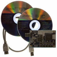
KIT MAX II MICRO
Manufacturer
Terasic Technologies Inc
Series
MAX® IIr
Type
FPGAr
Datasheet
1.P0305.pdf
(26 pages)
Specifications of P0305
Contents
Evaluation Board, Cable(s), Software and Documentation
For Use With/related Products
EPM2210F324
Lead Free Status / RoHS Status
Lead free / RoHS Compliant


Pushbutton switches
Clock inputs
Prototyping Areas
2.3
The complete schematic can be found in the Schematic folder of MAX II Micro System CD-ROM.
The following sections describe the major parts of the schematic in detail.
2.3.1
The MAX II Micro board provides four pushbutton switches. Each of these switches is debounced
using a Schmitt Trigger circuit, as indicated in Figure 2.3. The four outputs called KEY0, …, KEY3
of the Schmitt Trigger device are connected directly to the MAX II CPLD. Each switch provides a
high logic level (3.3 volts) when it is not pressed, and provides a low logic level (0 volts) when
depressed. Since the pushbutton switches are debounced, they are appropriate for use as clock or
reset inputs in a circuit.
There are 8 user-controllable LEDs on the MAX II Micro board. Each LED is driven directly by a
pin on the MAX II CPLD; driving its associated pin to a high logic level turns the LED on, and
driving the pin low turns it off.
4 pushbutton switches
Debounced by a Schmitt trigger circuit
Normally high; generates one active-low pulse when the switch is pressed
50-MHz oscillator
A 40-pin expansion port area compatible with Altera DE2/DE1 expansion ports.
Prototyping Area A with 68 GPIO, 6 3.3V, 2 5V and 8 GND pins
Prototyping Area B with 20 GPIO, 2 3.3V, and 2 GND pins
S chematic of the MAX II Micro Board
5 B
L EDs, Switches, and Clock Inputs
6 B
Figure 2.3. Switch debouncing.
6
MMK User Manual
Related parts for P0305
Image
Part Number
Description
Manufacturer
Datasheet
Request
R

Part Number:
Description:
MODULE DIGITAL CAMERA 5MP (D5M)
Manufacturer:
Terasic Technologies Inc
Datasheet:

Part Number:
Description:
DE2-70 CALL FOR ACADEMIC PRICING
Manufacturer:
Terasic Technologies Inc
Datasheet:

Part Number:
Description:
USB BLASTER CABLE
Manufacturer:
Terasic Technologies Inc
Datasheet:

Part Number:
Description:
BOARD ADAPTER HSMC TO GPIO
Manufacturer:
Terasic Technologies Inc
Datasheet:

Part Number:
Description:
BOARD ADAPTER THDB-SUM
Manufacturer:
Terasic Technologies Inc
Datasheet:

Part Number:
Description:
KIT DEV 4.3" LCD TOUCH PANEL
Manufacturer:
Terasic Technologies Inc
Datasheet:

Part Number:
Description:
DAUGHTER BOARD AD/DA GPIO ADA
Manufacturer:
Terasic Technologies Inc

Part Number:
Description:
DAUGHTER BOARD AD/DA HSMC ADA
Manufacturer:
Terasic Technologies Inc

Part Number:
Description:
BOARD DEV/EDUCATION ALTERA DE0
Manufacturer:
Terasic Technologies Inc
Datasheet:

Part Number:
Description:
BOARD DEV DE1 ALTERA
Manufacturer:
Terasic Technologies Inc
Datasheet:

Part Number:
Description:
DE2 CALL FOR ACADEMIC PRICING
Manufacturer:
Terasic Technologies Inc

Part Number:
Description:
MODULE DIGITAL CAMERA 1.3MP
Manufacturer:
Terasic Technologies Inc
Datasheet:

Part Number:
Description:
SENSOR CMOS 1.3MEGA (FOR P0349)
Manufacturer:
Terasic Technologies Inc
Datasheet:
Part Number:
Description:
MODULE DIGITAL CAMERA 5MP (D5M)
Manufacturer:
Terasic Technologies Inc
Datasheet: