P0305 Terasic Technologies Inc, P0305 Datasheet - Page 6
P0305
Manufacturer Part Number
P0305
Description
KIT MAX II MICRO
Manufacturer
Terasic Technologies Inc
Series
MAX® IIr
Type
FPGAr
Datasheet
1.P0305.pdf
(26 pages)
Specifications of P0305
Contents
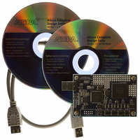
Evaluation Board, Cable(s), Software and Documentation
For Use With/related Products
EPM2210F324
Lead Free Status / RoHS Status
Lead free / RoHS Compliant


This chapter presents the features and design characteristics of the MAX II Micro board.
2.1
A photograph of the MAX II Micro board is shown in Figure 2.1. It depicts the layout of the board
and indicates the location of the connectors and key components.
Altera USB Blaster
The following hardware is provided on the MAX II Micro board:
Controller Chipset
USB Blaster Cable
Prototyping Area A
24 MHz Oscillator
USB Blaster Port
10-pin Header
(PROTO_A)
L ayout and Components
3 B
Altera MAX
USB Blaster (on board) for programming; MAX II Micro can be used as a USB Blaster, and
programming mode supported depends on the configuration device of Altera board
connected to MAX II Micro. Only JTAG programming mode is supported to configure
MAX II Micro.
4 pushbutton switches
1 DIP switch
2 red user LEDs
2 yellow user LEDs
2 green user LEDs
Altera MAX II Micro Board
®
II EPM2210F324 FPGA device
Figure 2.1. The MAX II Micro board.
Chapter 2
USB Blaster / MAX II
Power Mode Switch
4
4 Push-Button Switches
MMK User Manual
Prototyping Area B
(PROTO_B)
Altera MAX II
EPM2210 FPG A Device
50 MHz Oscillator
8 User LEDs
Related parts for P0305
Image
Part Number
Description
Manufacturer
Datasheet
Request
R

Part Number:
Description:
MODULE DIGITAL CAMERA 5MP (D5M)
Manufacturer:
Terasic Technologies Inc
Datasheet:

Part Number:
Description:
DE2-70 CALL FOR ACADEMIC PRICING
Manufacturer:
Terasic Technologies Inc
Datasheet:

Part Number:
Description:
USB BLASTER CABLE
Manufacturer:
Terasic Technologies Inc
Datasheet:

Part Number:
Description:
BOARD ADAPTER HSMC TO GPIO
Manufacturer:
Terasic Technologies Inc
Datasheet:

Part Number:
Description:
BOARD ADAPTER THDB-SUM
Manufacturer:
Terasic Technologies Inc
Datasheet:

Part Number:
Description:
KIT DEV 4.3" LCD TOUCH PANEL
Manufacturer:
Terasic Technologies Inc
Datasheet:

Part Number:
Description:
DAUGHTER BOARD AD/DA GPIO ADA
Manufacturer:
Terasic Technologies Inc

Part Number:
Description:
DAUGHTER BOARD AD/DA HSMC ADA
Manufacturer:
Terasic Technologies Inc

Part Number:
Description:
BOARD DEV/EDUCATION ALTERA DE0
Manufacturer:
Terasic Technologies Inc
Datasheet:

Part Number:
Description:
BOARD DEV DE1 ALTERA
Manufacturer:
Terasic Technologies Inc
Datasheet:

Part Number:
Description:
DE2 CALL FOR ACADEMIC PRICING
Manufacturer:
Terasic Technologies Inc

Part Number:
Description:
MODULE DIGITAL CAMERA 1.3MP
Manufacturer:
Terasic Technologies Inc
Datasheet:

Part Number:
Description:
SENSOR CMOS 1.3MEGA (FOR P0349)
Manufacturer:
Terasic Technologies Inc
Datasheet:
Part Number:
Description:
MODULE DIGITAL CAMERA 5MP (D5M)
Manufacturer:
Terasic Technologies Inc
Datasheet: